FREE 1 to 3-Day Delivery on Orders $149+ Details

How to Install Lange Crank Hoist-a-Top (07-18 Wrangler JK) on your Jeep Wrangler
Installation Time
4 hours
Tools Required
- Cordless Drill
- Level
- Stud Finder
- Ratcheting Wrench
- 9/16,11/16,5/16 Socket or Wrench
- 2x6 Standard Lumber (Length Depending on Stud Spacing)
- 3" Construction Screws
- Tape Measure
- Ladder
- Electrical Tape
Shop Parts in this Guide
To speed installation first determine the direction of your ceiling joists in reference to your garage door opening (Parallel or Perpendicular). Next take a measurement to determine if you have 16” OC or 24” OC spacing between ceiling joists. For joists running parallel cut (4) pieces of 2x6 lumber to an appropriate length in order to span the distance between joists. For perpendicular ceiling joists you will need to cut (1) piece of 2x6 lumber to a length long enough to span at least 3 ceiling joists. An additional (2) pieces of 2x6 lumber will need to be cut to length depending on your stud spacing (16”OC or 24” OC).
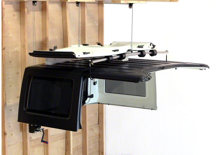
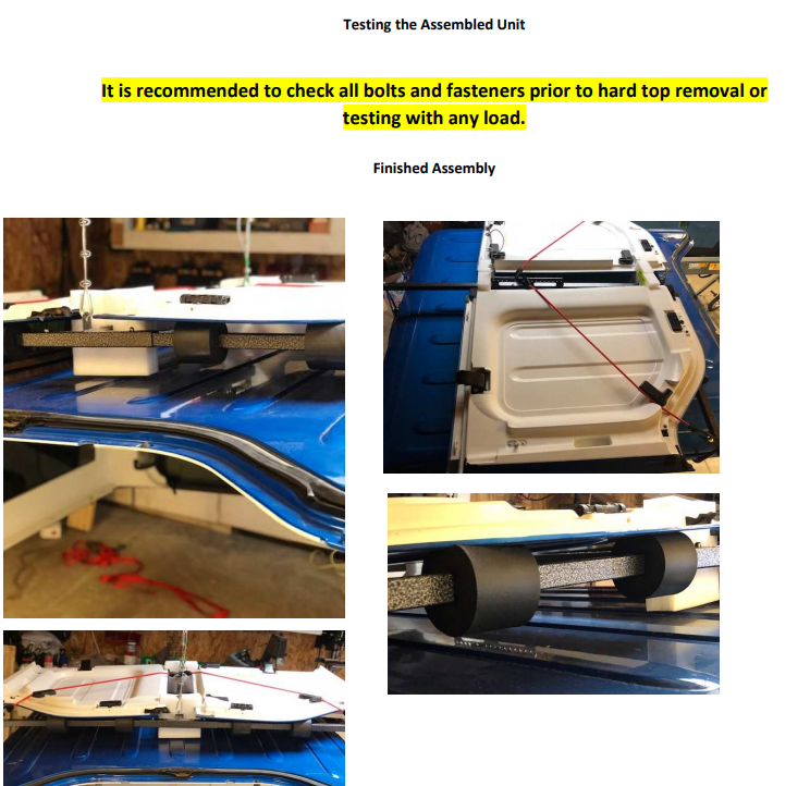
Assembling the Frame
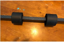
1. Slide two round foam bumpers onto each of the two supplied arms and space them evenly. These will be adjusted at a later time to support the Freedom top panels.
2. Depress the spring loaded button and insert each of the two arms into the main frame assembly to form a “T” shape. Next insert the remaining arm into the remaining opening and adjust each arm to the proper hole layout depending on the model of jeep. All hole settings may need to be adjusted based on your model of jeep and/or any modifications to your top (roof racks, etc.) that may affect the balance of your top when lifted.
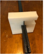
3. Slide smaller square foam piece down the main shaft of the “T” assembly with the slots facing up with the smaller slot on the left hand side. The proper orientation of this is crucial to making sure the Freedom panels fit securely.
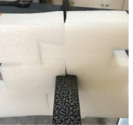
4. Now assemble the remaining larger form pieces with the fingers oriented upwards and the smaller slot on the left hand side like the previous foam piece. Be sure to leave the assembled foam piece behind the tab with multiple mounting holes to ensure it does not interfere with cable operation.
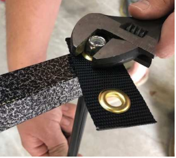
5. Locate the hooks and insert them through the holes at the ends of the left and right arms with the black straps with the grommets and secure with nylon nut as shown. Do not over tighten, hooks should remain loose with at least 3-5 threads extending beyond the nylon portion of the nut.
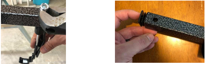
6. Attach the rear hook assembly as shown using the supplied nylon nut. Be sure not to overtighten as adjustment will be necessary during hard top removal. Insert square plugs into the exposed ends of the tubes.
7. Attach elastic straps to the grommets then to the main frame for now. These will be used later to secure the Freedom Panels to the frame prior to lifting off the top.
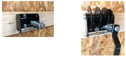
Mounting the Crank
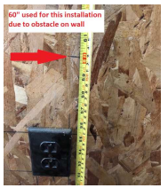
1. Start by securing one of the 2x6 pieces of lumber that was already measured and sourced. Measure 50” up from the floor and mark. This measurement can be moved up or down to adjust to obstacles on the wall or for varying heights of the end user. Using 3” construction screws (not supplied) attach the 2x6 to the wall studs making sure it is level and attached to at least 2 separate studs using 4-6 of the 3” construction screws.
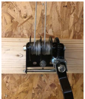
2. You will need to remove the spool to gain access to the mounting holes for the crank assembly. Locate the crank unit and remove the center spool using the 11/16 & 9/16 wrenches or sockets.
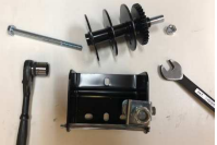
3. Mount the crank assembly using the (2) supplied 3” lag screws and washers. Once mounted reinsert the spool and attach the supplied handle as shown.
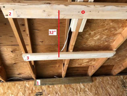
Mounting the pulleys (Perpendicular) ceiling joists pictured.
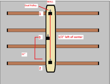
1. Mount (1) of the sourced 2x6 pieces of lumber to the wall directly above the crank assembly where the ceiling meets the wall. Fasten using 3” construction screws (not included). Using the remaining (2) pcs of 2x6 mount one on the mark that was identified as the center point of the hardtop from the preinstallation instructions. The last piece should be mounted approx. 32” OC from the center board.
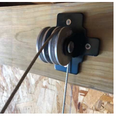
2. Mount the dual pulley in the center of the 2x6 (number 1 in the photo above) using the supplied screws (4). Next mount a single pulley in the center of the 2x6 (number 2 in the photo above) using supplied screws (4).
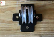
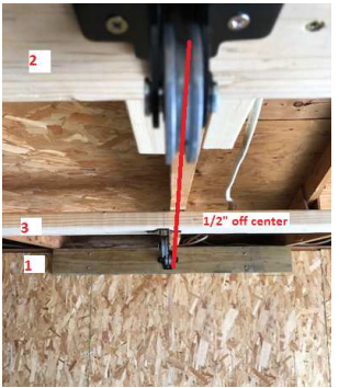
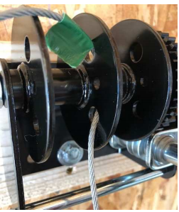
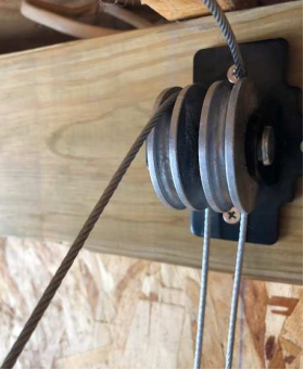
3. The final single pulley will be mounted ½” left of center on the 2x6 (number 3 in photo above) using the supplied screws (4). The final pulley mounting locations should look like the photo below.
4. For Parallel ceiling joist configuration the mounting locations will be the same for all 3 of the pulleys, but pulleys 1, 2 & 3 referenced above will be attached to a single longer 2x6 mounted to the ceiling joists. Make sure to select a length that is at least long enough to span several ceiling joists while still allowing for a spacing of 32” between pulleys 2 & 3 and making sure that pulley 3 is ½” left of center. See diagram below.
Installing the Cable
1. Mark one end of the cable with electrical tape then measure 20’ down the cable and mark with another piece of electrical tape. This will leave the cable with 20’ on one side of the tape with the marked end and 23’ on the other side.
2. Starting with the marked end of the tape (20’ side) insert the cable into one of the larger holes on the spool of the crank assembly from left to right. Pull until you reach the tape at the 20’ mark.
3. Locate the same end of the cable and pull it back through another hole in the spool from right to left.
4. Take the opposite end of the cable (non-marked 23’ side) and insert it into the spool from left to right through the remaining hole. This will result in the longer side being on the right (gear side) and the shorter end (marked end) being on the left side of the spool.
5. Loop the longer cable (side closest to gear) over the right side of the dual pulley and continue to pull the cable skipping the first single pulley (½ “off center) and loop over the last single pulley. This cable will be attached to the front of the frame that was previously assembled.
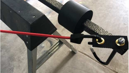
6. Loop the cable through the front mounting tab on the assembled frame and tighten using the supplied hardware as shown.
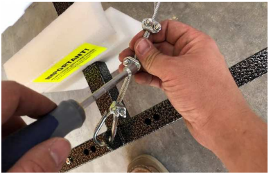
7. Loop the shorter end of the cable over the left side of the dual pulley on the wall and pull remaining slack through. This cable will then loop over the first of the single pulleys (½ “off center).
8. Using the supplied hardware connect to one of the rear mounting holes on the frame assembly and tighten as you did on the front.
Note: You may need to move this connection point to find the proper balance for your top based on an initial test.
9. Use the crank to begin coiling up excess cable making sure that the cable is winding evenly onto the corresponding side of the spool. As the slack is wound up make sure that the empty frame is being lifted evenly. Adjustment may be necessary to ensure even lifting between the front and back of the frame.
Installation Instructions Written by ExtremeTerrain Customer Jerry Birdsong 06/01/2018.