FREE 1 to 3-Day Delivery on Orders $149+ Details

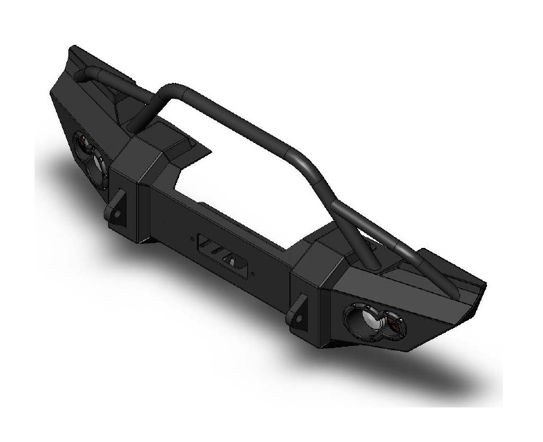
How to Install Fab Fours JK Lifestyle Winch Bumper w/ Guard on your 07-18 Jeep Wrangler JK; 2018 Jeep Wrangler JL
Installation Time
1 hours
Tools Required
- Regular Screwriver
- Phillips Screwdriver
- Socket Wrench With Extension
- 18mm Socket
- 19mm Socket
- 7/16” Open End Wrench
- 5/32” Allen Wrench

Vehicle Preparation
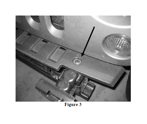
A) Remove (4) dart clips from underside of OEM bumper/skid plate.
B) Remove (2) dart clips from back side of plastic skid plate.
C) Disconnect fog light harness from back of each fog lamp (if applicable).
D) Remove (8) nuts from bumper studs using 18mm socket.
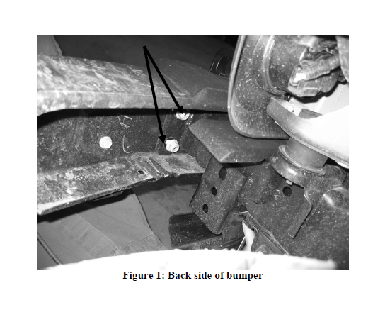
E) Slide bumper forward slightly so that the studs still pass through frame but
the bumper rocks forward. Remove fog harness retainer clips from bumper.
F) Remove OEM bumper and set aside.
G) Remove two dart clips from top bumper trim plastic using Phillips screwdriver. Set trim aside as it will not be re-used.
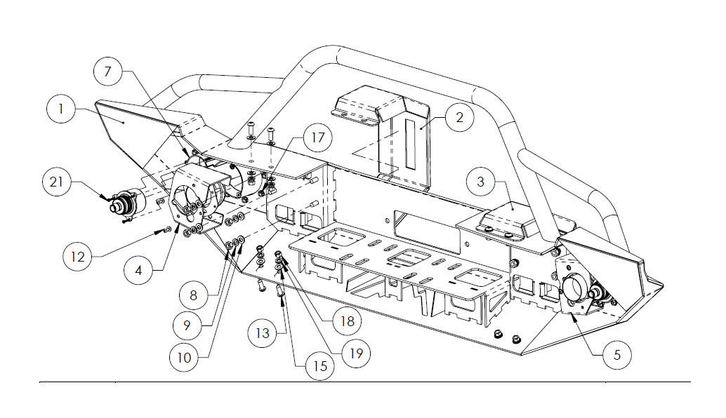
Bumper Preparation
A) Install turn signal into light pockets using self-tapping screws as shown below.
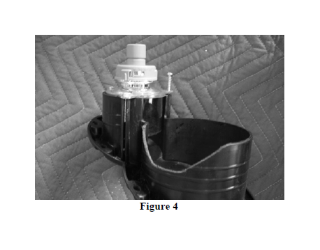
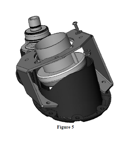
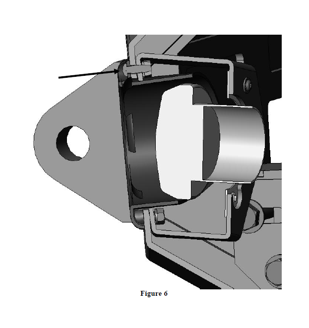
B) Install fog lamp into brackets as shown using #10-32 bolts and nuts. Be sure to align large cutout in light bracket with adjuster screw on light assembly, and with the v-shaped cutout on the light insert.
C) Install light pocket into bumper through front face, align corresponding fog lamp/bracket from back side. Secure with 10 (each side) button head screws as shown. Verify that light alignment adjusters are on bottom of light assembly. Repeat for other side.
D) Attach harnesses to fog lamps – see wiring section for details.
E) Install rubber edge trim on trim caps – no adhesive necessary as compression will secure trim.
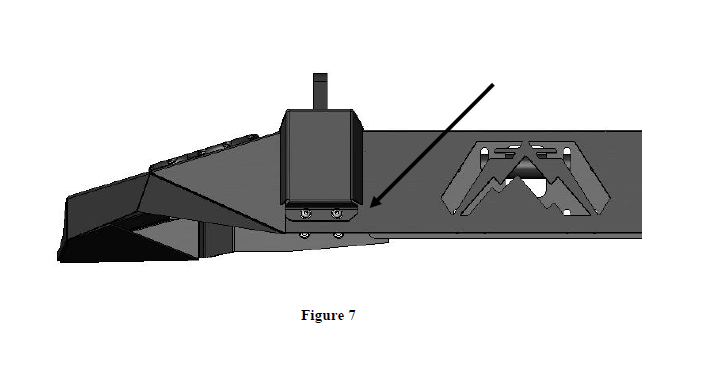
F) Install trim caps as shown using 3/8” stainless steel hardware. Verify that flat edge is inward when viewed from bottom of bumper.
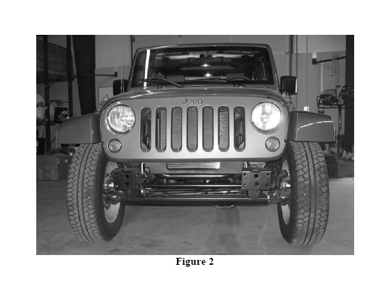
Bumper Installation
A) Lift bumper and align mounting studs with holes in frame face plate.
B) Secure loosely with (8 each) 10mm flat washer, lock washer and nut. Do not tighten fully.
C) Because of the mounting system, little adjustment is necessary. Verify proper alignment and tighten all fasteners.
D) If installing winch, do so now. Follow instructions provided with winch. Remember to install fairlead onto front of bumper.
Lights and wiring installation
Turn Indicator
A) On each side, disconnect light connector and tap into the three turn indicator wires using supplied tap connectors (reference the wiring diagram).
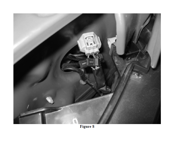
B) Connect supplied turn indicator wiring harnesses to tap connectors following wiring diagram; repeat for other side.
C) After turn indicator harnesses are attached to turn indicators, fill the indicator plug with RTV or other silicone sealant to ensure moisture does not enter plug.
Headlight
D1) Optional: Install Hella® light harness per installation instructions provided.
D2) Tap into OEM headlight wires (low beam) at the headlight connector following wiring diagram - use two supplied tap connectors. Repeat for other side.
E) Connect supplied fog lamp wiring harness to tap connectors following wiring diagram. Repeat for other side.
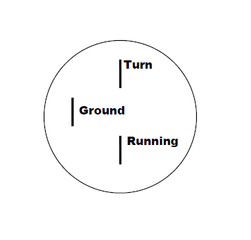
Wiring Diagram
Note: Colors May Vary
Passenger Side Turn Indicator at Headlight
OEM (Running) – Minor – White/Tan→White Fab Fours
OEM (Turn) – Major - White/Tan →Red Fab Fours
OEM (Ground) Blk→Green Fab Fours
Driver Side Turn Indicator at Headlight
OEM (Running) – Minor – White/Light Green →White Fab Fours
OEM (Turn) – Major – White/Light Green→Red Fab Fours
OEM (Ground) White/Blk→Green Fab Fours
Driver Fog Lamp
OEM (Power) Red/Yellow →Red Fab Fours
OEM (Ground) Blue →Green Fab Fours
Passenger Fog Lamp
OEM (Power) Blue/Red →Red Fab Fours
OEM (Ground) Red/Wht →Green Fab Fours
Note: Tap into Fab Fours driver side fog lamp harness to supply passenger side
Hella Turn Indicator Connectors
Maintenance/Care
Periodically check and tighten all fasteners.
Stripped, fractured, or bent bolts or nuts need to be replaced.