 FREE 1 to 3-Day Delivery on Orders $149+ Details

How to Install Vision X 6.7" LED Light Cannon Kit for your 87-18 Jeep Wrangler YJ, TJ, JK & JL
WIRING INSTALLATION
1. Find a suitable place to mount Relay [Part R1] leaving enough room for Power & Ground Wire [Parts W1 & W2] to reach the Battery & the Deutsch Connector Wiring [Parts C1 & C2] to reach the Lights. Mount Relay.
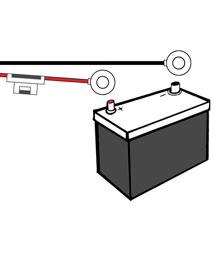
2. Run Power Wire [Part W1] & Ground Wire [Part W2] to the Battery. Connect the Power Wire [Part W1] to the Positive ( ) Battery Terminal and connect the Ground Wire [Part W2] to the Negative (-) Battery Terminal.
3. Run the Deutsch Connector Wiring [Parts C1 & C2] to each Light and Plug in. It doesn’t matter which Deutsch Connector plugs into which Light.
4. Unplug Power Wire [Part W3] from the Toggle Switch [Part S1]. Run Power Wire [Part W3] to the Vehicles Fire Wall at the point that you will bring the Wire through to the inside of the Cab (using a Factory Rubber or Plastic Grommet is suggested). Run Power Wire [Part W3] to the inside of the Cab. Note: This Wire can be extended if necessary.
5. Find a suitable place to Drill the Hole needed to mount the Toggle Switch [Part S1] and Continue to run the Power Wire [Part W3] to that location. Plug the Power Wire [Part W3] into Outside Pin of Toggle Switch [Part S1]. It doesn’t matter which Outside Pin you use.
6. Drill the Hole to the required size for the Toggle Switch [Part S1]. Mount Toggle Switch [Part S1] to in desired position.
MANUFACTURER RECOMMENDATION
For those unfamiliar with electrical wiring on vehicles, Vision X recommends that all LED Lighting products are professionally installed.

COMPONENTS KEY
Part (R1) Relay Part (W1) Ground Wire for Relay Coil a. 12 Volt Negative (-) Input Wire
Part (W2) Power Wire for Relay Coil a. 12 Volt Positive ( ) Input Wire
Parts (C1 & C2) Deutsch Connectors for Lights a. Attached to12 Volt Positive ( ) Power Wires
Part (W3) Power Wire for Relay Input a.12 Volt Positive ( ) Input Wire [Part R1]
Part (S1) Toggle Switch
MOUNTING INSTALLATION
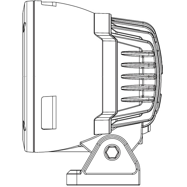
1. Determine where the light/lights will be placed.
2. Hold mounting bracket with light to desired mounting surface. Using a marker or pick tool, mark the bolt hole on the desired mounting surface.
3. Set the light aside. Find the center point of the hole you have marked out and drill out a large enough hole to fi t the 5mm bolt [Part M1].
4. Remove the Mounting Bracket from Light by unscrewing the (2) 5mm Allen Head Bolts [Part M4], one on each side.
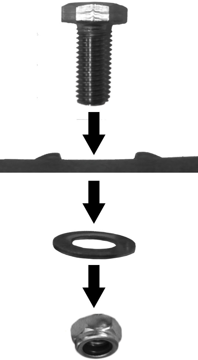
5. Set Bracket down on Desired Mounting Surface, Lining up the Hole in the center of Mounting Bracket with the Hole you just Drilled, Slide 5mm Bolt [Part M1] through both.
6. On the other side of Mounting Surface slide 5mm Washer [Part M2] and 5mm Nylock Nut [Part M3] onto 5mm Bolt. [Part M1] Tighten Nut [Part M3] & Bolt [Part M1] to Desired Tightness.
7. Hold Light in Mounting Bracket while screwing in the (2) 5mm Allen Head Bolts [Part M4], one on each side. Use 5mm Allen Key [Part M5] to tighten both 5mm Allen Head Bolts [Part M4] to Desired Tightness.
LIGHT ANGLE ADJUSTMENT
1. Use the 5mm Allen Key [Part M5] to loosen each of the Allen Head Bolts [Part M4] on either side of the light.
2. Adjust the light until you have your desired angle.
3. Then, tighten the Allen Head bolts [Part M4] to hold the desired position.
WARNING: Bolts, Nuts, and Washers are Stainless Steel. DO NOT USE Pneumatic or Electric Tools to Tighten and Loosen. The Hardware Will Permanently Lock Together.