FREE 1 to 3-Day Delivery on Orders $149+ Details

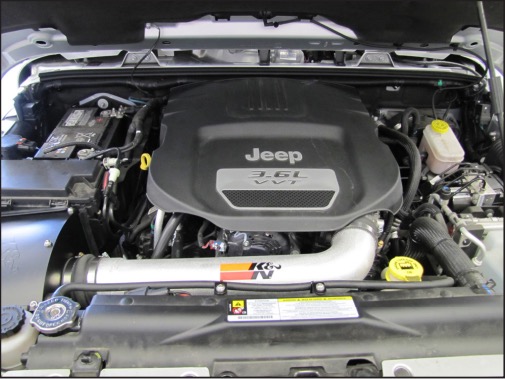
How to Install a K&N Series 77 High Performance Intake on your 2012-2017 Jeep Wrangler JK 3.6L
Installation Time
1 hours
Tools Required
- Flat blade screw driver
- Ratchet, Extension
- 10mm socket
- 12mm wrench
- 10mm wrench
- 4mm Allen

Shop Parts in this Guide
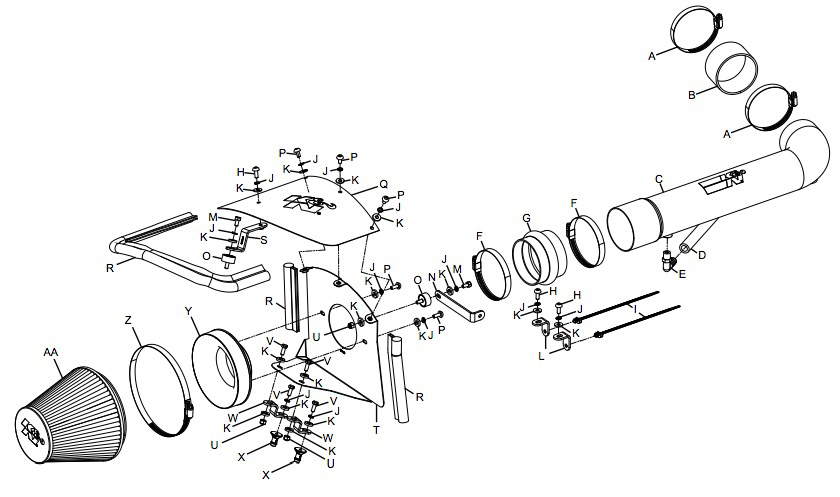
PARTS LIST:
NOTE: This kit was not designed to fit vehicles with a body lift.
NOTE: FAILURE TO FOLLOW INSTALLATION INSTRUCTIONS AND NOT USING THE PROVIDED HARDWARE MAY DAMAGE THE INTAKE TUBE, THROTTLE BODY AND ENGINE.
TO START:
1. Turn off the ignition and disconnect the negative battery cable.
NOTE: Disconnecting the negative battery cable erases pre-programmed electronic memories. Write down all memory settings before disconnecting the negative battery cable. Some radios will require an anti-theft code to be entered after the battery is reconnected. The anti-theft code is typically supplied with your owner’s manual. In the event your vehicles’ anti-theft code cannot be recovered, contact an authorized dealership to obtain your vehicles anti-theft code.
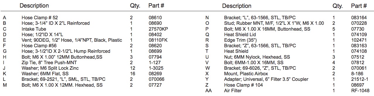
2. Lift up and remove the engine cover.
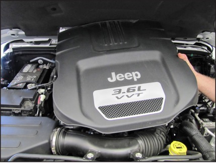
3. Remove the two bolts which secure the factory intake tube to the fan shroud.
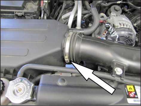
4. Loosen the hose clamp securing the factory intake tube to the air filter housing.
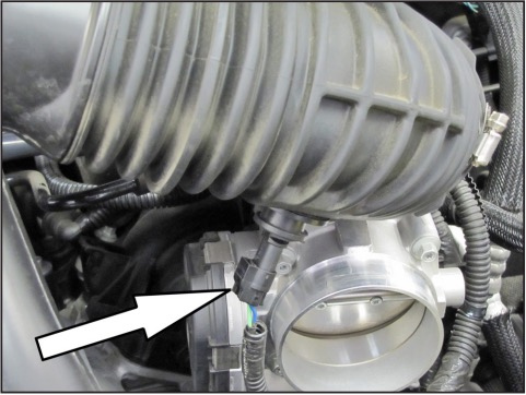
5. Loosen the hose clamp securing the factory intake tube to the throttle body.
6. Lift up the intake tube and then disconnect the inlet air temperature electrical connection. Then remove the intake tube from the vehicle.
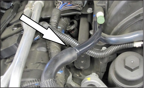
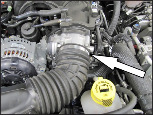
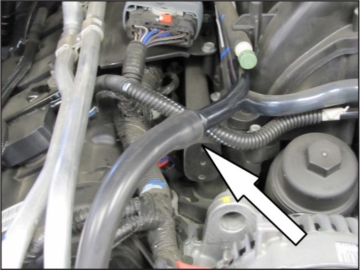
7. Disconnect the crank case vent hose from the crank case vent tube.
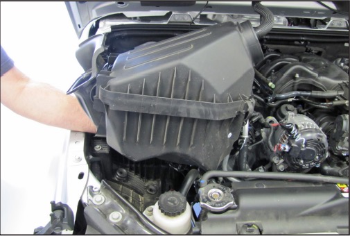
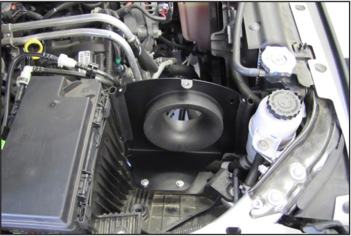
8. Lift up and remove the air filter housing from the vehicle
NOTE: K&N Engineering, Inc., recommends that customers do not discard factory air intake.
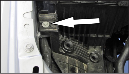
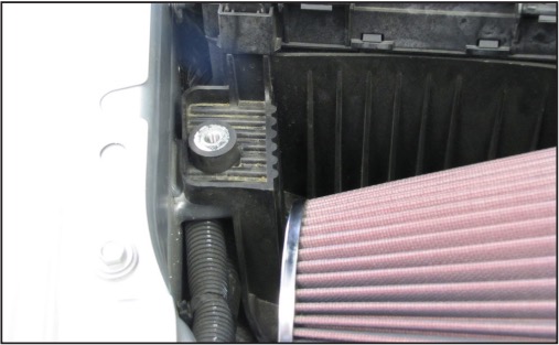
9. Remove the bolt shown that secures the air box mount bracket to the inner fender.
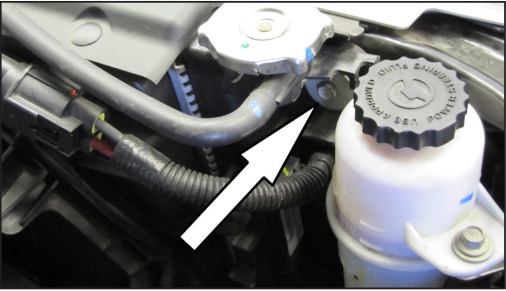
10. Remove the bolt shown that secures the radiator to the core support.
NOTE: This bolt will be reused in a later step
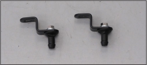
11. Install the two provided mounting studs onto the two heat shield brackets (070061) as shown.
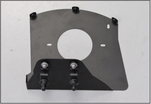
12. Install the two heat shield bracket assemblies onto the heat shield as shown.
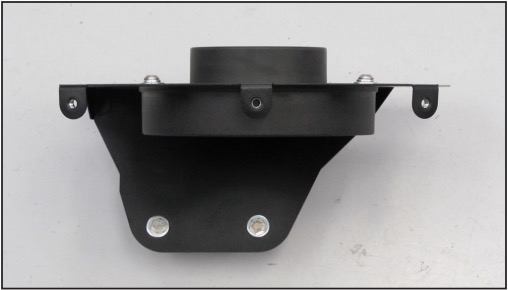
13. Install the provided filter adapter onto the heat shield as shown.
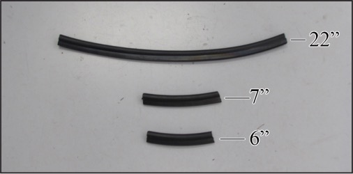
14. Cut the provided edge trim into three sections. One section is to be 6” long, one section is to be 7” long and the final section is to be 22” long.
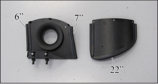
15. Install the edge trim onto the heat shield and lid as shown.
16. Install the heat shield assembly into position so the mounting studs are in the air box mounting grommets.
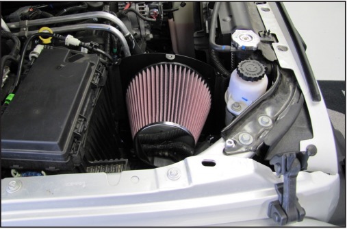
17. Install the K&N® air filter onto the filter adapter and secure with the provided hose clamp.
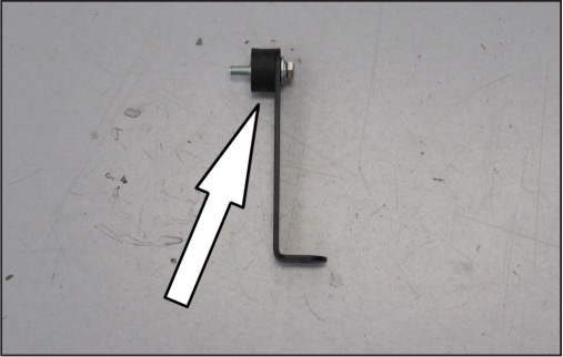
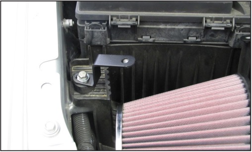
18. Install the provided rubber mounted stud onto the heat shield bracket (083164) as shown.
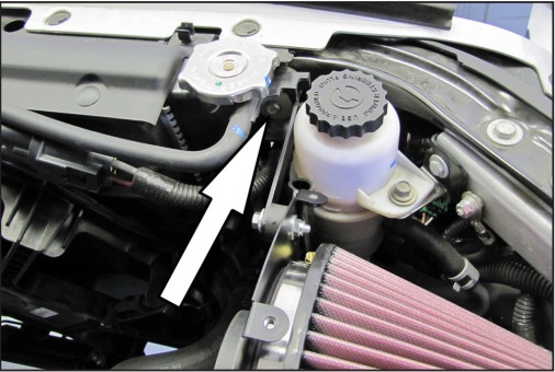
19. Install the heat shield bracket assembly onto the heat shield and radiator mount as shown. Secure the bracket with the factory bolt from step number 9 and the hardware provided.
20. Install the rubber mounted stud into the into the air box mounting plate bolt location as shown.
21. Install the provided bracket (083163) onto the rubber mounted stud using the provided hardware.
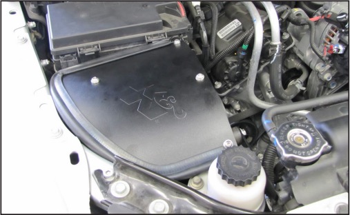
22. Install the K&N® filter lid and secure with the provided hardware.
NOTE: Install the bolt into the bracket 1st
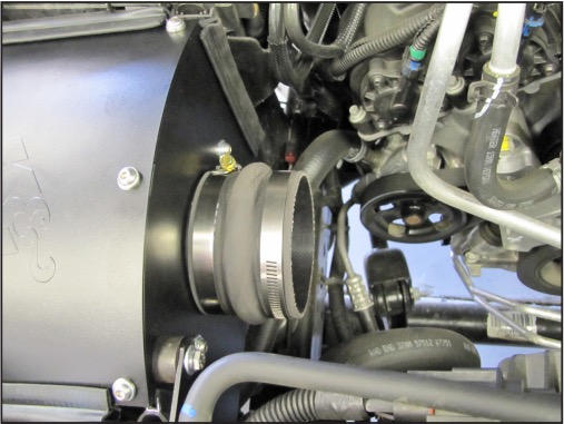
23. Install the provided hump hose (08699) onto the filter adapter and secure with the provided hose clamp.
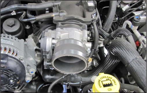
24. Install the provided silicone hose (08690) onto the throttle body and secure with the provided hose clamp.
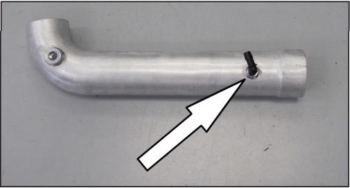
25. Install the 90º, ½” vent fitting into the K&N® intake tube as shown.
NOTE: Plastic NPT fittings are easy to cross thread. Install the vent fitting “hand” tight, then turn it two complete turns with a wrench.
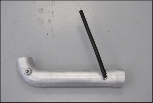
26. Install the provided crank case vent hose onto the fitting as shown
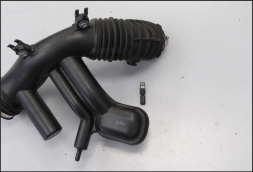
27. Remove the inlet air temperature sensor from the factory intake plenum as shown.
NOTE: Use caution working with the inlet air temperature sensor as it is very fragile.
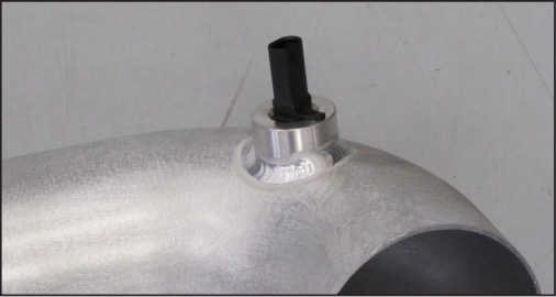
28. Install the inlet air temperature sensor into the K&N® intake tube as shown.
NOTE: Align the tab on the sensor with the line on the sensor mount then rotate clockwise to lock into position.
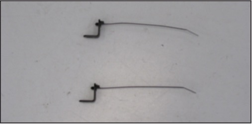
29. Install the two provided mounting head tie wraps into the two provided brackets (070066) as shown.
NOTE: The tie wraps are to be installed into the round holes.
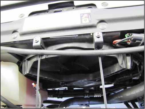
30. Install the tie wrap equipped brackets onto the factory intake tube mounting locations on the fan shroud using the provided hardware. Then secure the coolant over flow hose with the tie wraps.
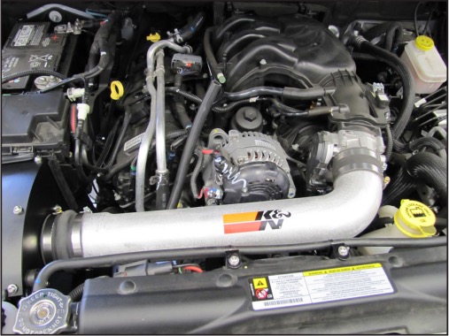
31. Install the K&N® intake tube into the silicone hose at the filter adapter and then into the hose at the throttle body, then secure with the provided hose clamps.
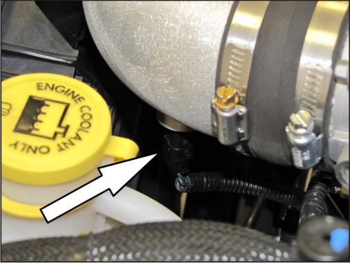
32. Connect the open end of the crank case vent hose to the factory crank case vent tube as shown.
33. Reconnect the inlet air temperature sensor electrical connection and then reinstall the engine cover.
34. Reconnect the vehicle’s negative battery cable. Double check to make sure everything is tight and properly positioned before starting the vehicle.
35. It will be necessary for all K&N® high flow intake systems to be checked periodically for realignment, clearance and tightening of all connections. Failure to follow the above instructions or proper maintenance may void warranty.
ROAD TESTING
1. Start the engine with the transmission in neutral or park, and the parking brake engaged. Listen for air leaks or odd noises. For air leaks secure hoses and connections. For odd noises, find cause and repair before proceeding. This kit will function identically to the factory system except for being louder and much more responsive.
2. Test drive the vehicle. Listen for odd noises or rattles and fix as necessary.
3. If road test is fine, you can now enjoy the added power and performance from your kit.
4. K&N Engineering, Inc., requires cleaning the intake system’s air filter element every 100,000 miles. When used in dusty or off-road environments, our filters will require cleaning more often. We recommend that you visually inspect your filter once every 25,000 miles to determine if the screen is still visible. When the screen is no longer visible some place on the filter element, it is time to clean it. To clean and re-oil, purchase our filter Recharger® service kit, part number 99-5050 or 99-5000 and follow the easy instructions.