FREE 1 to 3-Day Delivery on Orders $149+ Details

How to Install Rugged Ridge Dual Battery Relay Kit on your 87-18 Jeep Wrangler YJ, TJ, JK & JL

Shop Parts in this Guide
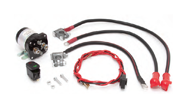
Kit Contents:
1. Isolator Relay
2. Dual position switch
3. Switch wiring harness
4. ( ) Battery post clamp
5. (-) Battery post clamp
6. Battery cables (3)
7. Relay mounting hardware
PLEASE READ AND UNDERSTAND ALL INSTRUCTIONS BEFORE YOU BEGIN
Notice: Safety glasses, gloves and protective clothing should be worn when working around batteries.
Disconnect cables from the battery before you begin.
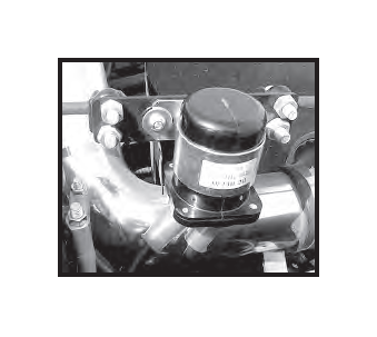
Step 1. Mount the Dual Battery Isolator.
When using Rugged Ridge Dual Battery Trays use the following locations: CJ-(76-86), YJ-(87-95) Mount the Isolator to the battery hold down bar. TJ-(97-06) Mount the Isolator to the bracket on the radiator core support rod (As shown). JK-(2007 Up) Mount the Isolator to the battery tray below the evap solenoid.
When not used with a Rugged Ridge Dual Battery Tray you will need to find a suitable secure mounting location.
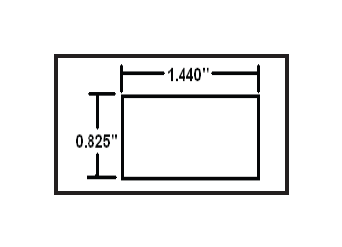
Step 2. Mount the Rocker switch in a suitable location.* The switch requires a square mounting hole cut to the dimensions provided in the illustration.
*Rugged Ridge switch housing are available. Sold separately.
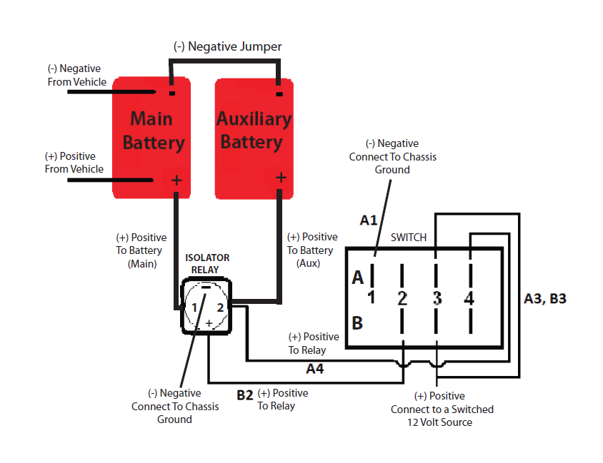
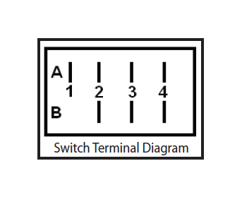
Step 3. Wiring the switch. Connect one end of the supplied ground wire to terminal A1 and the other end to a good chassis ground. Connect one of the long red wires from terminal A4 to the #2 post on the Isolator Relay. Connect one of the long red wires from terminal B2 to the ( ) post on the relay. Locate the supplied wire with the inline fuse, connect the end of the wire with 2 spade terminals to the A3 and B3 terminals on the switch. Connect the other wire to a switched positive lead that only has power when the ignition key is in the on position. See diagram on page 2 for further wiring information.
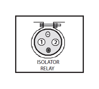
Step 4. Wiring the Isolator Relay. Connect the small (-) wire to the small (-) position post on the relay, connect the opposite end to a chassis ground. Connect the short (-) cable to the auxiliary battery using the supplied (-) battery clamp, connect the opposite end to the main battery negative clamp. Tighten and secure both (-) clamps. Connect one of the long ( ) cables to the auxiliary battery using the supplied ( ) battery clamp, connect the opposite end to the #2 position post on the relay. Connect the other ( ) cable to the #1 position post on the relay, connect the other end to the ( ) on the main battery. Tighten and secure all ( ) connections. Check all wires to ensure the do not touch any hot or sharp surfaces. Test the system for proper function.
All L. E. D.’s off- System is off and in factory mode.
Green L. E. D. on- System is on (Normal mode). Starts and runs with main battery. Charges both batteries with ignition on.
Red L. E. D. on- System is on (Emergency mode). Both batteries are connected. Joins both batteries for Starting or Winching when main battery is dead or vehicle motor is inoperative.