 FREE 1 to 3-Day Delivery on Orders $149+ Details

How to Install Mopar Auxiliary Switch Bank (2018 Jeep Wrangler JL, Excluding Rubicon) on your Jeep Wrangler
Installation Time
6 hours
Tools Required
- Flathead and Phillips Head Screwdriver
- Trim Tool (Not required; can make installation easier/reduce ability to damage parts and pop clips)
- Socket Set (1/4 inch, 5.5mm, 10 mm, 13mm)
- Cutters
- Pliers
- Pick
- Tape (Electrical or Duct)
- Wire Coat Hanger
Note: This installation was performed on a 2018 JL Jeep Wrangler Sport S
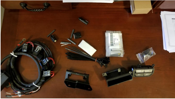
1. Open package, ensure all parts are present.
2. On the passenger side of the vehicle locate the rivets holding on the inner-fender splash guard. Remove four rivets starting closest to the passenger seat. To remove rivets, pop them out a bit and snip them off using cutters.
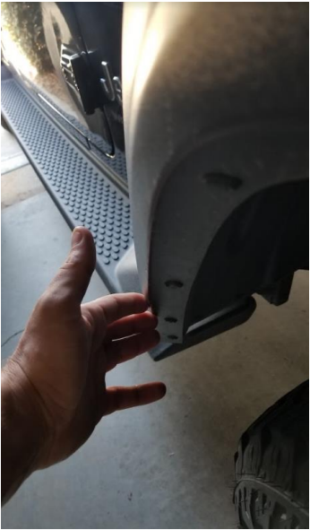
3. Remove the two push-pin pop-clips on the inside of the fender well using a flathead screwdriver.
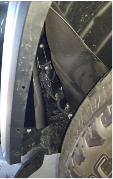
4. Pull back inner fender liner and secure behind wheel.
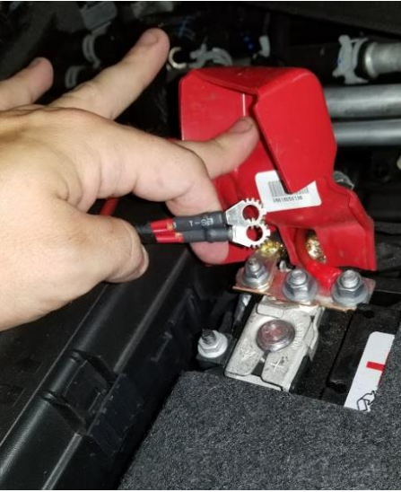
5. Disconnect the main battery negative terminal.
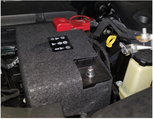
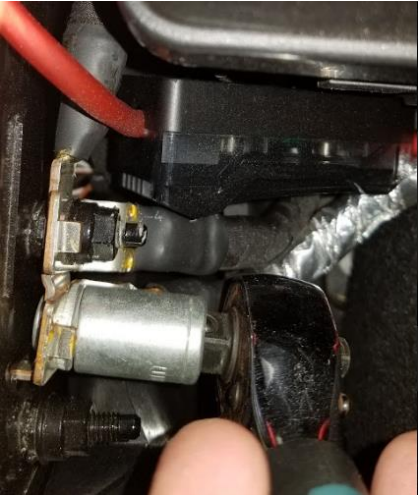
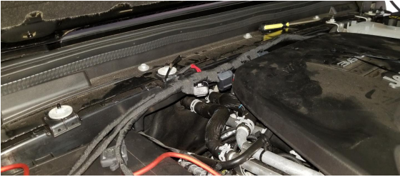
6. Disconnect the ground isolators using a 10 mm socket and a 13 mm socket and safely secure them with a rag or towel. Remove the entire bracket. This is located next to the battery.
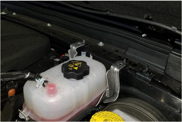
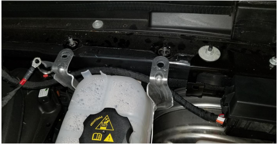
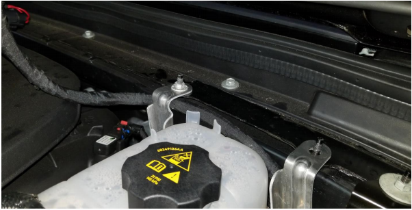
7. Move to the other side of the engine bay, drivers side. Remove the three nuts holding on the coolant tank.
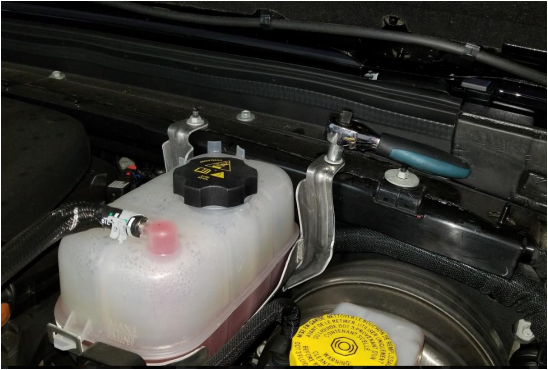
8. Pull up coolant tank off housing screws to make room for the new wiring harness included with installation kit.
9. Install the power distribution bracket as shown on the rightmost studs. Use the new nut included with your installation kit to secure.
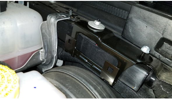
10. Install the new power distribution center onto the mount previously installed by locking the back of the PDC into the rightmost bracket holster.
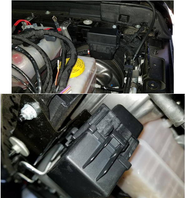
11. Run wires from power distribution block to the battery, underneath the coolant tank.
12. Reattach coolant tank to studs and retighten screws to hold tank into place.
13. Run wires towards battery, using included zip ties to attach the wire and fuses to the back plastic panel.
14. Attach positive leads from PDC to battery.
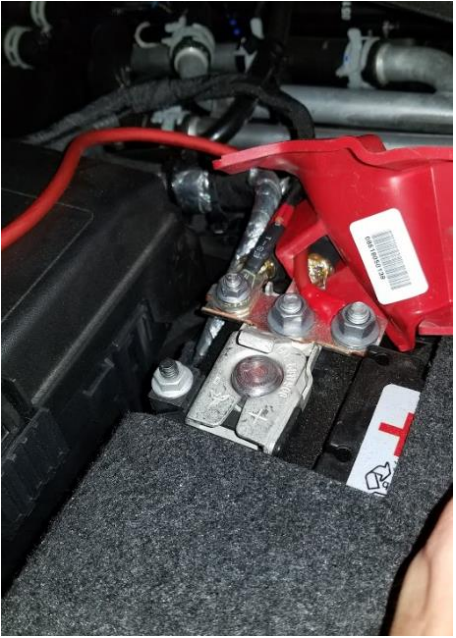
15. Install PDC ground to the third ground screw next to where the previous ground isolators were removed in step 6.
16. Leave the auxiliary hot connections on the outside of the vehicle. Tuck them near the battery to keep them out of place.
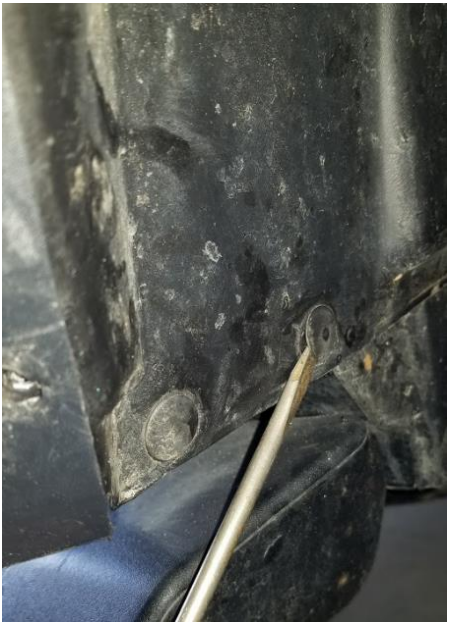
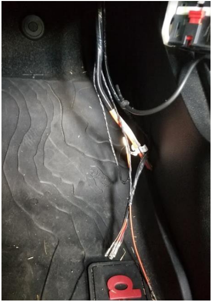
17. Using the wires from the PDC that are not the auxiliary hot connections tucked away in previous step, fish them down past the battery and pull them through to the passenger’s side fender well. Locate the main bulkhead inside the fender well.
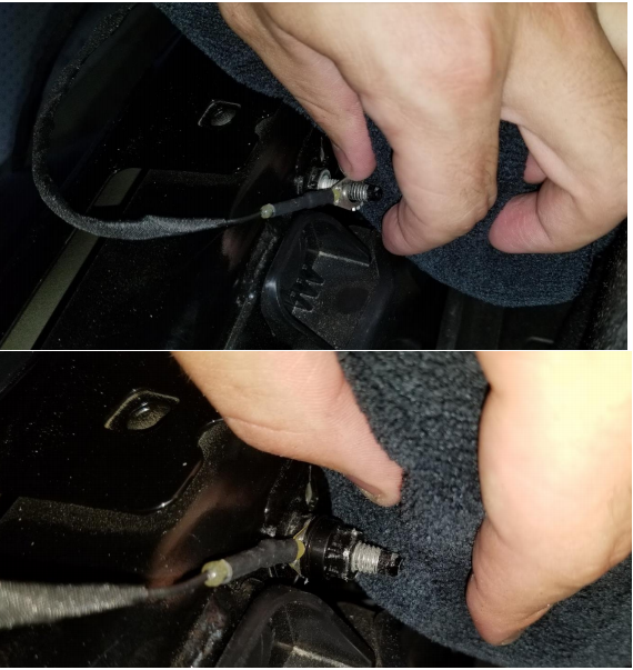
18. Using a well lubricated metal coathanger, push the coat hanger through the rubber grommet from the fender well. Once this is complete, attach a wire to the coat hanger and pull it back through to the fender well.
19. Attach your PDC wires securely to the fishing wire, lubricate well, and carefully pull your fishing wire through the bulkhead firewall grommet.
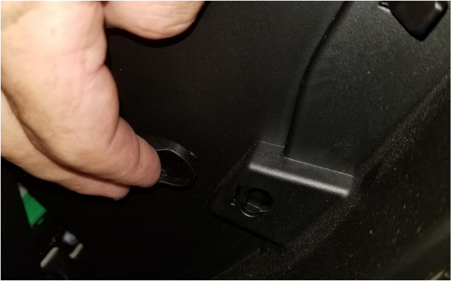
20. Remove panel leading to the door electronics hub, disconnect door electronics and door swing stop.
21. Pulling from the back of the bottom kick panel, pull hard to pop the clips on the bottom kick panel and remove entirely.
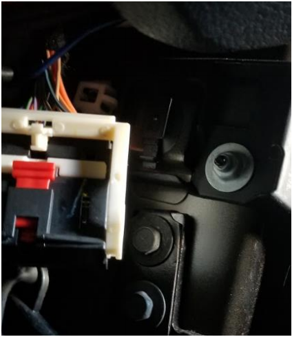
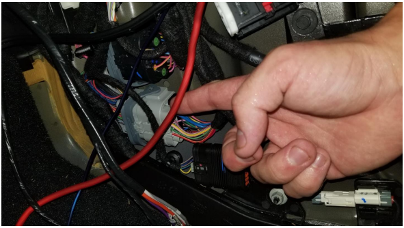
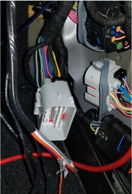
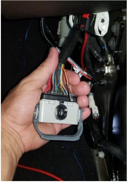
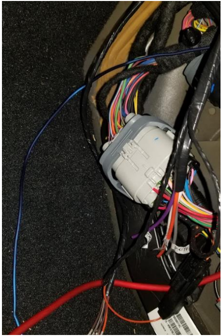
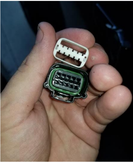
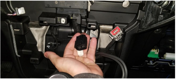
22. Find the internal gray electronics connector. Disconnect by moving the grey swing bar up and pulling on the other end, similar to how door electronics are disconnected.
23. Carefully remove the red safety harness from the female connector using a flathead screwdriver.
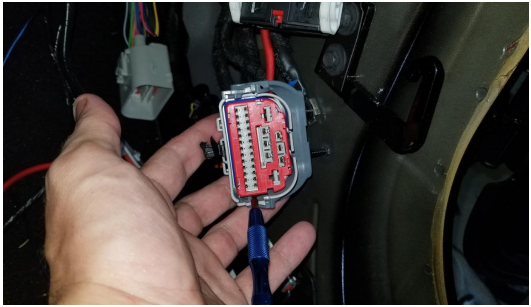
24. With the clip facing upward, find the bottom two rows of connectors. Count over five from the end of the panel and use a pick to push this connector out through the bottom of the hub.
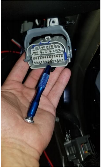
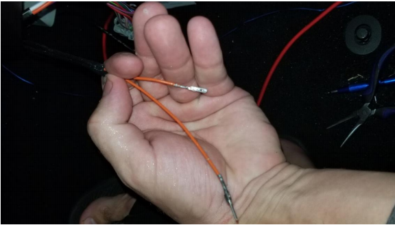
25. To finish removing the orange wire from this harness, flip the harness over and find the solid orange wire. If the previous step of pushing the orange wire out of the harness was done correctly, pull out the orange wire carefully from the harness.
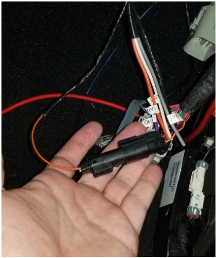
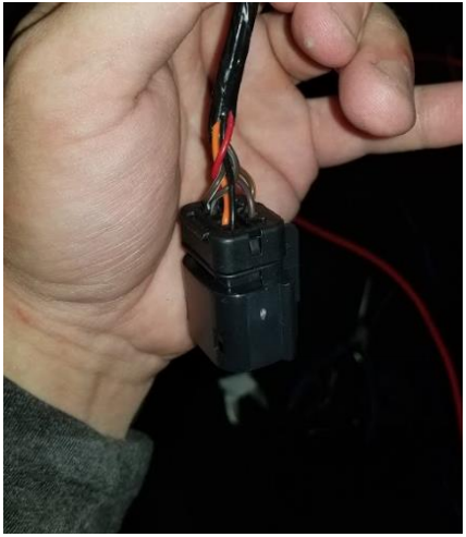
26. Find the new orange wire connectors from the PDC fished through the firewall and locate the female end of the connector.
27. Using a pair of needle nose pliers, carefully insert this new female orange connector into the electronics hub.
28. For the original orange wire pulled from the hub earlier (female connection), push this wire securely into the female connector unit included with your install kit. Insert this wire into slot one (labeled on connector), and insert a plastic blank (included with kit) into the other side.
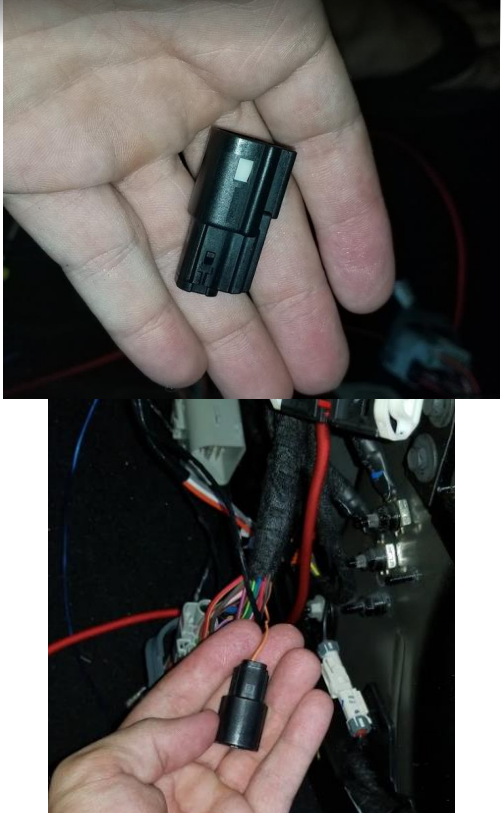
29. Using the male, unused wire from your PDC, carefully insert this wire into the male connector kit on the same side as you did on your previous step, and insert a plastic blank into the other side.
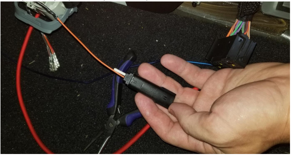
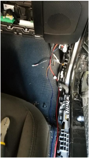
30. Secure the connection and zip tie out of the way.
31. Reconnect electronics hub.
32. Place the four auxiliary connections (hots for inside the car) out of the way until you are ready to use them.
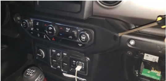
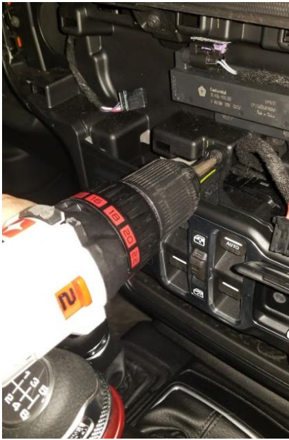
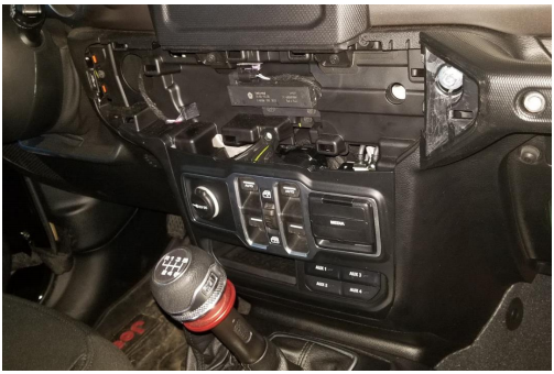
33. Begin removing the dash by placing a flathead screwdriver carefully on the side of the unit and prying around until the clips pop out.
34. Remove electronics from removed front panel bezel for both integrated electronics and push to start.
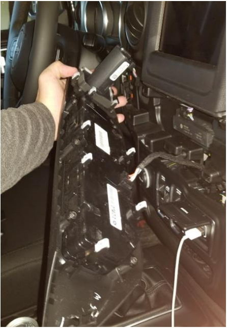
35. Remove singular Phillips Head screw holding in bottom panel.
36. Pop out bottom panel and all connected electronics connections.
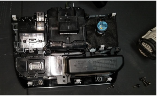
37. Move bottom panel to another workspace, and remove the 5 mm screws holding in the bottom cubby.
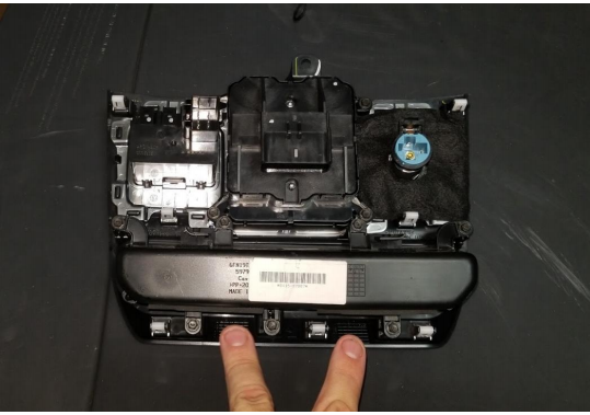
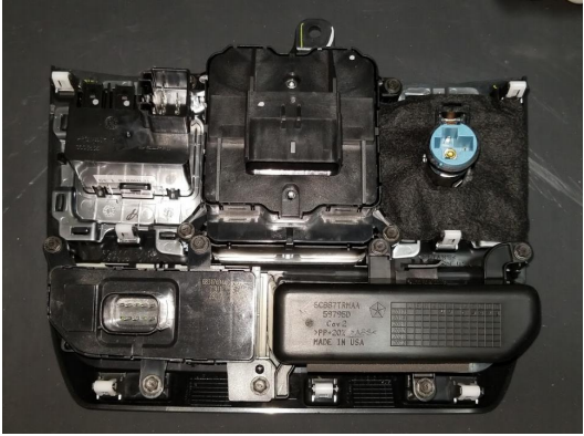
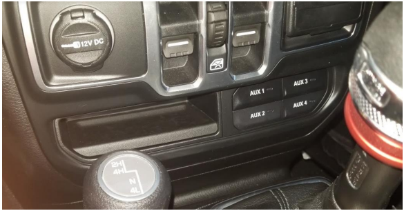
38. Install the new switch and cubby included with your kit inside the bottom panel, reattaching factory screws.
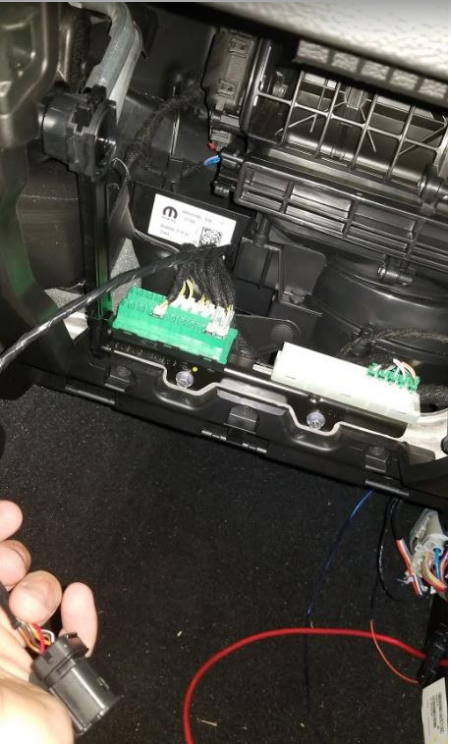
39. Moving back to the wires fished through from the PVC, find the switch bracket and carefully pull out the safety bracket.
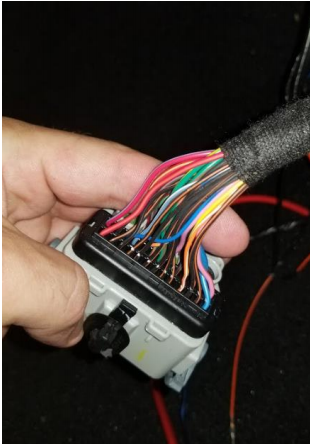
40. Note the numbered connections on the back of this hub. Place the wires securely into the unit, a click will be heard when seated correctly. Use the following numbers for the colors:
a. Orange – 9
b. Red – 1
c. Brown/White – 6
d. Brown/Purple– 4
e. Brown/Grey – 7
f. Brown/Orange – 3
g. Black – 10
41. Once complete, put safety clip back into harness unit.
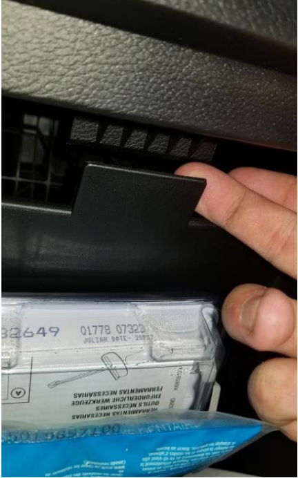
42. Remove glovebox by unlatching clip at the bottom left of the glovebox.
43. Complete glovebox removal by pulling on clip at the top and pulling glovebox through.
44. Route the previous wiring harness that was created for the aux switch panel through the glovebox area and through to the main dash area to connect to aux switch panel.
45. Reconnect lower electronics including aux switch electronics harness, reaffix Phillips screw to hold in lower dash panel.
46. Reattach top console electronics and push back into place securing the clips.
47. Perform steps removing kick panel, door electronics, glovebox, door swing latch, battery disconnection, ground disconnection, wheel well trim, etc. in reverse to revert to previous state. Be sure to use the new rivets included with your kit to affix interior wheel well trim back to factory state.
Complete
Installation Instructions Written by ExtremeTerrain Customer Zack M. 9/12/18
