 FREE 1 to 3-Day Delivery on Orders $149+ Details

How to Install a JKS Front Or Rear Adjustable Swaybar End Link Kit on your 2007-2017 Jeep Wrangler
Installation Time
45 minutes
Tools Required
- Metric/Standard Socket Wrench Set
- Torque Wrench
- Tape Measure
- Angle Measuring Tool
- 3/4" Open-End Wrench
- 14mm & 15mm Open End Wrenches
- Medium Strength Threadlocker
- Metal Cutting Tool (such as die grinder with cutting wheel or appropriate saw for cutting connecting rod)
- Metal Grinding Tool* (such as die grinder with metal cutting wheel)
- 17/32" Drill Bit
- Satin Black Spray Paint
- Factory Service Manual (recommended)

Shop Parts in this Guide
Welcome
CONGRATULATIONS on purchasing a set of new Adjustable End Links from JKS Manufacturing. We are committed to providing you with the best products available and your satisfaction is our first priority.
PLEASE READ these Installation Instructions carefully, and save them for future reference, as they contain important installation and maintenance information.
Important
NOT COMPATIBLE WITH aftermarket swaybars. Install product with Original Equipment swaybar only.
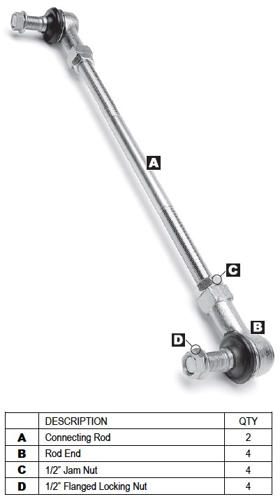
Parts
Rear Installation
1. REMOVE ORIGINAL EQUIPMENT (OE) REAR SWAYBAR LINKS
Remove the original mounting hardware that secures the rear swaybar links to the swaybar and axle.
Discard original rear swaybar links and mounting hardware.
2. DETERMINE PROPER LENGTH OF ADJUSTABLE END LINKS
The Adjustable End Links can be adjusted to any length between 8.75” and 15” (measured from center-to-center of rod ends). However, it is critically important to set the length correctly for your application.
If the End Links are too long, they will contact the brake lines running along the chassis, which could lead to complete brake system failure. If the End Links are too short, they will limit suspension travel at full extension.
Adhere to the following instructions carefully to ensure that your Adjustable End Links are set to the correct length.
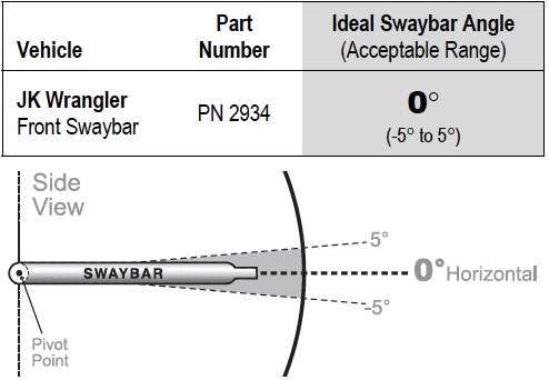
Rotate the rear swaybar to the Ideal Angle (or within Acceptable Range) listed below. Vehicle must be at normal ride height and located on level ground.
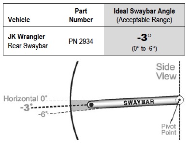
While holding the swaybar at the proper angle, measure the distance between the center of the original mounting holes on the swaybar and axle bracket.
Subtract 2.25” from the distance recorded above to determine the correct length of the Connecting Rod (A). HINT: For instance, if the center-to-center distance for your application is 10”, the Connecting Rod length should be 7.75”.
3. MODIFY CONNECTING ROD
Now that you know the correct Connecting Rod (A) length for your application, subtract the length from the overall Connecting Rod length of 12.75” and then divide by 2 to determine the amount of material to remove from each end.
HINT: For instance, if the correct Connecting Rod length for your application is 7.75”, the amount of material to remove from each end will be 2.5”. Example 12.75 - 7.75 = 5 and 5 ÷ 2 = 2.5”
Remove Rod Ends (B) from both ends of the Connecting Rod (A). Do not remove 1/2” Jam Nuts (C).
Using the value provided by the formula above, mark each end of the Connecting Rod (A) to indicate the appropriate locations to cut.
HINT: Remove same amount of thread material from each end.
Using an appropriate cutting tool (such as a die grinder with cutting wheel, or metal cutting saw), carefully and squarely cut each end of the Connecting Rod (A) where previously marked.
Now completely unthread both 1/2” Jam Nuts (C) from Connecting Rod (A) and re-install.
HINT: This will help to repair any thread damage that may have occurred during the cutting process.
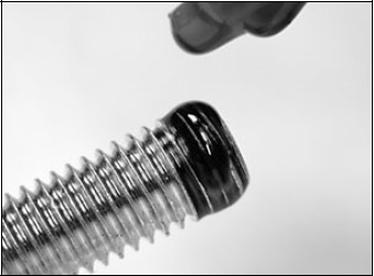
Apply a drop of medium strength thread locking compound to the tip of threads at each end of Connecting Rod (A).
Completely thread a Rod End (B) on to each end of Connecting Rod.
4. INSTALL END LINKS
Using the supplied 1/2” Flanged Locking Nuts (D), secure the Adjustable End Links to the swaybar and axle bracket. Make sure upper and lower Rod Ends (B) are in alignment with their respective mounting surfaces.
IMPORTANT: End Links must be installed on outboard side of swaybar and axle bracket.
Once all adjustments are complete, fully tighten the Jam Nuts (C) against the Rod Ends (B) to prevent length of Adjustable End Links from changing.
Tighten the 1/2” Flanged Locking Nuts (D) to 40 ft-lbs. using a torque wrench.
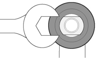
HINT: Use flat spot on Rod Ends (B) to prevent mounting stud from spinning when tightening 1/2” Flanged Locking Nut (D).
On the upper Rod Ends (B) only, cut the excess thread material from the mounting stud so that none of the threaded portion protrudes beyond Flanged Locking Nut (D).
On vehicles in which the rear axle housing has been rotated to correct the pinion angle following a CV driveshaft installation, there may be insufficient clearance between the upper control arm bracket on the axle and the Connecting Rod (A).
Check for interference where indicated by the arrow in the illustration below.
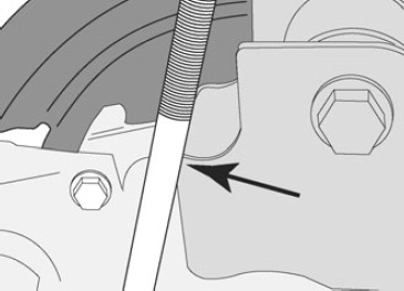
If interference between the control arm bracket and Connecting Rod (A) is discovered, it will be necessary to clearance the bracket per the following instructions.
Locate the area of interference and mark the location on both upper control arm brackets.
Temporarily remove the Adjustable End Link from the swaybar to provide access to the control arm bracket.
Remove just enough material from the control arm bracket to prevent the Connecting Rod (A) from contacting it. HINT: A die grinder or metal grinding wheel is useful for removing material from the control arm bracket.
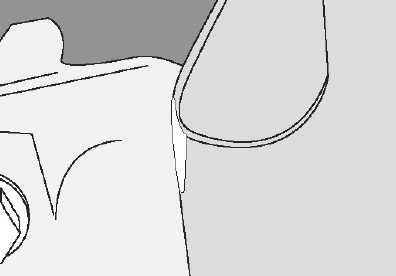
IMPORTANT: It should not be necessary to grind all the way through the steel bracket. Only remove enough material to eliminate the interference problem.
Once sufficient clearance has been established, apply spray paint to any bare metal on control arm bracket to prevent corrosion.
Reinstall Adjustable End Link on swaybar and tighten per the instructions earlier in this section.
5. TEST FOR INTERFERENCE
Before driving vehicle, compress the rear suspension to check for interference between the Adjustable End Links and chassis-mounted brake lines. If any interference occurs, take corrective action by utilizing one of the following methods:
Add or adjust bump stop height of rear suspension to prevent upper Rod Ends (B) from contacting brake lines.
Reduce length of Adjustable End Links by removing additional thread material from the Connecting Rod (A). Remove only as much thread material as necessary to eliminate interference. If Adjustable End Links are too short, rear suspension travel will be restricted.
Carefully bend the brake lines inward (toward chassis) to gain approximately 0.25” of additional clearance.
Front Installation
1. REMOVE ORIGINAL EQUIPMENT (OE) FRONT SWAYBAR LINKS
Remove the original mounting hardware that secures the front swaybar links to the swaybar and axle.
Discard original front swaybar links and mounting hardware.
2. DETERMINE PROPER LENGTH OF ADJUSTABLE END LINKS
The Adjustable End Links can be adjusted to any length between 8.75” and 15” (measured from center-to-center of rod ends). Adhere to the following instructions carefully to ensure that your Adjustable End Links are set to the correct length.
Rotate the front swaybar to the Ideal Angle (or within Acceptable Range) listed below. Vehicle must be at normal ride height and located on level ground.
While holding the swaybar at the proper angle, measure the distance between the center of the original mounting holes on the swaybar and axle bracket.
Subtract 2.25” from the distance recorded above to determine the correct length of the Connecting Rod (A). HINT: For instance, if the center-to-center distance for your application is 10”, the Connecting Rod length should be 7.75”.
3. MODIFY CONNECTING ROD
Now that you know the correct Connecting Rod (A) length for your application, subtract the length from the overall Connecting Rod length of 12.75” and then divide by 2 to determine the amount of material to remove from each end.
HINT: For instance, if the correct Connecting Rod length for your application is 7.75”, the amount of material to remove from each end will be 2.5”. Example 12.75 - 7.75 = 5 and 5 ÷ 2 = 2.5”
Remove Rod Ends (B) from both ends of the Connecting Rod (A). Do not remove 1/2” Jam Nuts (C).
Using the value provided by the formula above, mark each end of the Connecting Rod (A) to indicate the appropriate locations to cut. HINT: Remove same amount of thread material from each end.
Using an appropriate cutting tool (such as a die grinder with cutting wheel, or metal cutting saw), carefully and squarely cut each end of the Connecting Rod (A) where previously marked.
Now completely unthread both 1/2” Jam Nuts (C) from Connecting Rod (A) and re-install. HINT: This will help to repair any thread damage that may have occurred during the cutting process.
Apply a drop of medium strength thread locking compound to the tip of threads at each end of Connecting Rod (A).

Completely thread a Rod End (B) on to each end of Connecting Rod.
4. INSTALL END LINKS
If you are installing this product on a Rubicon model with electronic front swaybar disconnect, you must now enlarge the mounting holes on the swaybar using a 17/32” drill bit.
Using the supplied 1/2” Flanged Locking Nuts (D), secure the Adjustable End Links to the swaybar and axle bracket. Make sure upper and lower Rod Ends (B) are in alignment with their respective mounting surfaces.
IMPORTANT: End Links must be installed on outboard side of swaybar and inboard side of axle bracket.
Once all adjustments are complete, fully tighten the Jam Nuts (C) against the Rod Ends (B) to prevent length of Adjustable End Links from changing.
Tighten the 1/2” Flanged Locking Nuts (D) to 40 ft-lbs. using a torque wrench.
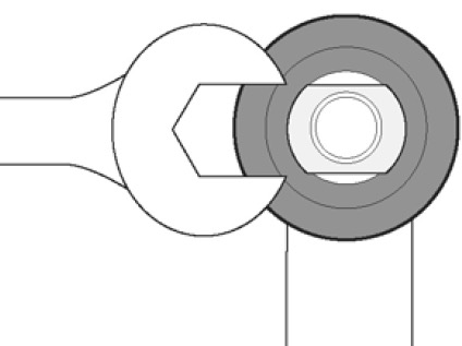
HINT: Use flat spot on Rod Ends (B) to prevent mounting stud from spinning when tightening 1/2” Flanged Locking Nut (D).

