 FREE 1 to 3-Day Delivery on Orders $149+ Details

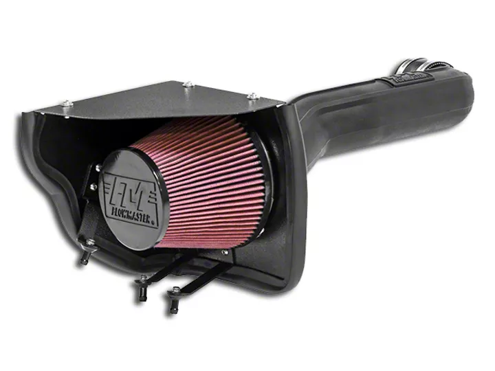
How to Install Flowmaster Delta Force Cold Air Intake (12-17 3.6L Wrangler JK) on your Jeep Wrangler
Shop Parts in this Guide
Removal:
Note: Please refer to vehicle manufacturer’s recommendations regarding removal of components.
1. Turn off the ignition and disconnect the negative battery cable. NOTE: Disconnecting the negative battery cable erases pre‐programmed electronic memories. Write down all memory settings before disconnecting the negative
battery cable. Some radios will require an anti‐theft code to be entered after the battery is reconnected. The anti‐theft code is typically supplied with your owner’s manual. In the event your vehicles’ anti‐theft code cannot be recovered, contact an authorized dealership to obtain your vehicles anti‐theft code.
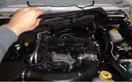
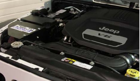
2. Remove the engine cover by grasping the front edge and lifting up, then pull forward. Unclip the coolant overflow hose from the air tube. We highly recommend that customers retain their factory air intake system.
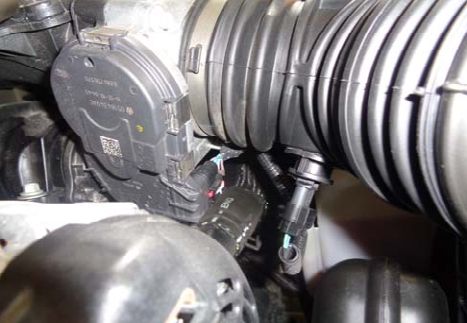
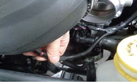
3. Disconnect the electrical plug from the air temperature sensor located on the underside of the intake tube near the throttle body by depressing the backside of the rocking tab and gently pulling away.
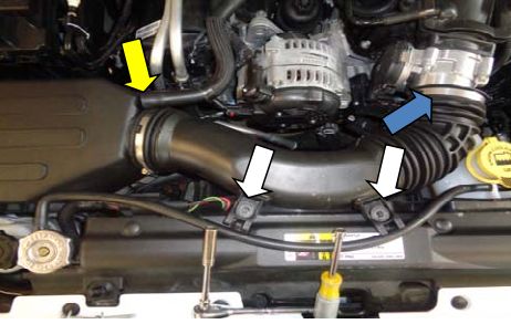
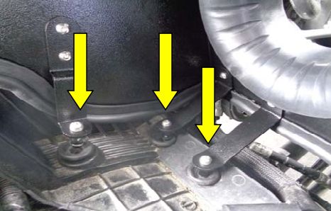
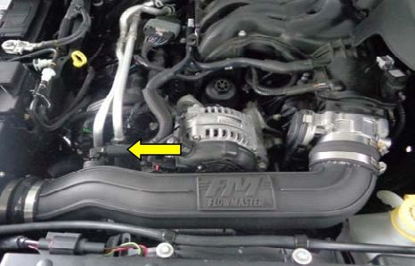
4. Loosen the hose clamp (blue arrow) securing the factory intake tube to the throttle body. Remove the two bolts (white arrows) securing the stock intake tube/resonator to the front cross frame and retain. Disconnect the crank‐case breather tube (yellow arrow) from the stock air‐box.
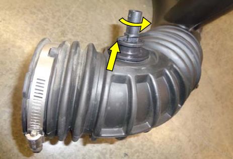
5. Remove the entire stock intake assembly from the vehicle by lifting straight up and out. Turn upside‐down on a flat surface and remove the air temp sensor from the intake tube by prying up the clocking tab with a flat screwdriver and rotating c‐clockwise.
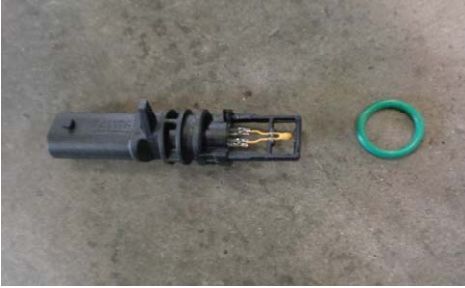
6. Remove the o‐ring from the air temperature sensor. Place a sensor‐safe grease or lubricant on the o‐ring surface to facilitate easier installation into the FM air intake tube grommet. Retain in a safe location.
Assembly:
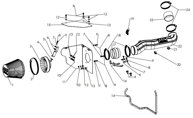
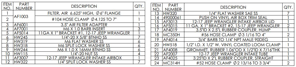
Assemble the FM Cold Air Intake using the drawing on the front page for reference.
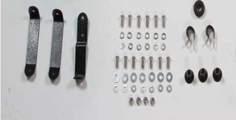
7. Begin assembly process of the FM cold air intake kit by removing all hardware and arranging by type and thread. This will facilitate an easier assembly process and lessen the chance of misplaced parts.
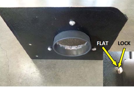
8. Begin by installing the air‐filter adapter onto the heat shield as shown. Fasten with three 6mm screws placing the flat and locking washers in the sequence shown. Tighten securely but avoid over‐torque.
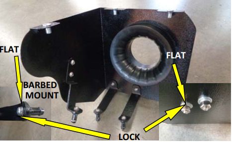
9. Install the metal brackets included in the kit using the supplied 1/4” screws/washers/nuts as shown. Then, install the barbed aluminum mounts onto the
metal brackets using the 6mm screws/washers.
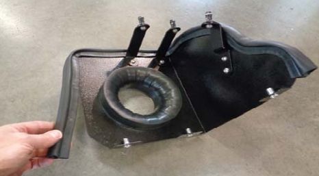
10. Install the rubber trim seal along the outer top and side edges as shown. Press fully into the groove starting from one end. Trim final length with metal shears for proper fitment
11. Install the heat shield assembly (minus the lid and FM intake tube) into the vehicle as shown above with the barbed mounts firmly pressed down until fully seated into the rubber grommets on the fender.
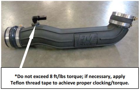
12. Loosely assemble the provided silicone‐rubber couplers and corresponding hose clamps and barbed fitting* onto the FM intake tube as shown above.
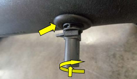
13. Insert the provided rubber grommet (yellow arrow) into the hole in the FM intake tube. Insert the pre‐lubed stock air temperature sensor into the grommet by twisting
clockwise and pressing inwards until seated as above.
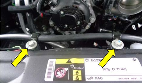
14. Use the retained stock front cross‐frame air tube/resonator bolts and the provided vinyl coated loom‐clamps to secure the coolant overflow tube to the cross‐frame. Do not over‐tighten.
15. Install the FM intake tube assembly onto the airbox and the throttle body*. Align and tighten all clamps for a satisfactory fit. Slip the crankcase vent hose onto the barbed fitting (yellow arrow) on the intake tube.
16. *Due to limited space for access, it may be necessary to attach the air temperature plug during the intake tube attachment process. Make sure that the plug fully engages the retaining tab on the sensor.
17. Secure the provided cone filter using the included hose clamp in the desired position. Using the last three ¼” screws/washers, secure the air‐box lid, reinstall the engine cover and the battery cable. Enjoy!
