 FREE 1 to 3-Day Delivery on Orders $149+ Details

CJ Gauge Troubleshooting
XT Staff
/ Feb 4 2026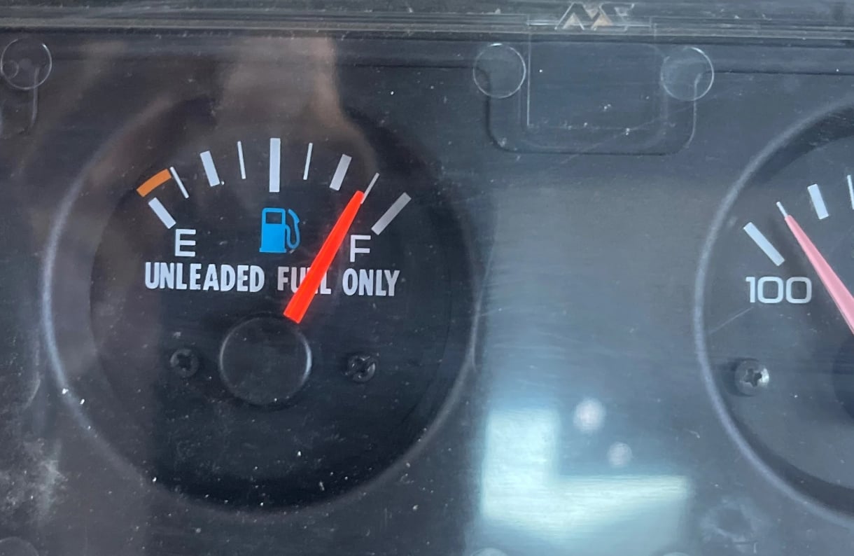
1972-1986 Jeep CJ's
Jeep CJ gauges, like all older Jeeps, will wear out over time. Troubleshoot Jeep CJ Gauges and prolong the life of the OEM parts with these simple techniques. If you see your temperature gauge not moving, you may be able to assess and repair the problem in no time. Likewise, get a Jeep CJ fuel gauge diagnosis with minimum stress, and keep your CJ dashboard in proper working order.
The following information, the image at the bottom of this article and a decent volt/ohm meter should help you do just that.
Understanding the Fuel and Temperature Gauges
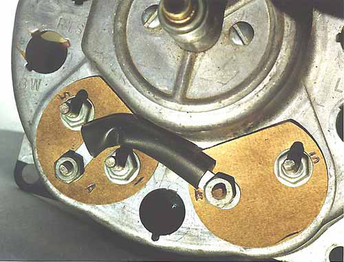
The fuel and temperature gauges shown below are laid out in a simple left to right configuration. Both Jeep parts gauges have wiring terminals and a large jumper/regulator strap running between them.
The fuel gauge terminals are labeled: S, A and I.

Fuel gauge S terminal has a pink wire and runs to the fuel sender. Fuel gauge A terminal is the 12V side of the jumper/regulator strap. Fuel gauge I terminal has a red wire and is the 12 V ignition hot wire.
The temperature gauge terminals are labeled: A and S.

Temperature gauge A terminal is the 5V side of the jumper/regulator strap. Temperature gauge S terminal has a purple wire and runs from the temperature sender.
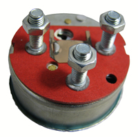
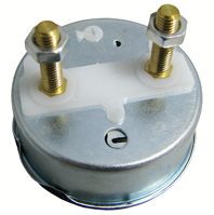
Back Side of Speedometer with Fuel and Temp Gauge
The jumper/regulator strap runs from a voltage regulator inside the fuel gauge (terminal A) to the temperature gauge (terminal A). A voltage reading at terminal A of the temperature gauge should be approximately 5 volts. A 12V reading here means you have a bad regulator.
The meter movement in all the gauges have a built-in dampening mechanism which keeps the needle from bouncing around. The dampening mechanism is basically some thick grease on the movement's pivot points.
The reason all the meters are dampened is because the senders do not have a very constant resistance. If you put a good testing meter on the sender while the motor is running you will see the resistance bounce all over the place. The dampening averages out the reading. This also is why it takes a few seconds for the needles to come up to position instead of snapping to a reading.
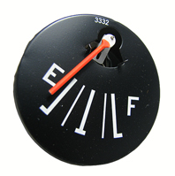
Fuel Gauge Resistance Readings
The fuel gauge should have the following resistances.
- S to Ground 68-72 ohms
- S to I 19-21 ohms
- S to A 19-21 ohms
- I to A Zero
- I to Ground 49-51 ohms
- A to Ground 49-51 ohms
The fuel sending unit wires are located on top of the gas tank where they are hard to get to without dropping the tank. The fuel sending unit should have a pink wire with voltage on the isolated center post. The other black wire on the sending unit with a tab style connector is a ground to the frame. Make sure it has good contact.
To be sure the problem is not the gauge, you can momentarily short the pink wire on the output of the sender to ground, and this should show up as FULL on your gauge. DO NOT hold it for very long in this position. If the gauge does not move from EMPTY either the wiring has an open circuit (no voltage, or no connection to ground) or he gauge is bad. If it does move, the sending unit is bad.
The sending unit can be checked with an ohmmeter to measure the resistance between the round sender post (pink wire) and ground. It should be:
| RESISTANCE | READING |
|---|---|
| 73 ohms | Empty |
| 23 ohms | 1/2 tank |
| 10 ohms | Full |
If the resistance falls in this ballpark (depending on how much gas you have in the tank), then the sending unit is fine. If it shows infinitely HIGH resistance, then the sending unit could be bad OR the wire from the tank to the gauge could be open.
The gauge can be tested with the resistances listed above. Run an appropriate resistor to the S terminal of the fuel gauge and to ground and check the readings.
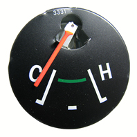
Temperature Gauge Resistance Readings
The temp gauge has the following resistance.
- S to A 19-21 ohms
A volt meter can be used to measure the voltage between the A terminal of the Temp gauge and ground. It should be pulsing and averaging about 5 volts. If it reads 12 volts the Jumper Strip/Regulator is bad. If it reads 0 volts, it has been burnt out.
The sending unit can be checked with the following resistances between the post and ground.
| Totally Cold | High Resistance |
| Slightly Warm | 73 ohms |
| Beginning of Band | 36 ohms |
| End of Band | 13 ohms |
| Hot | 9 ohms |
If an appropriate resistor is connected to the S terminal of the temperature gauge and to ground, the above restances can be used to check the gauge. Use a resistor close to the specifications above to simulate the sending unit.
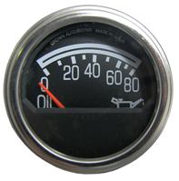
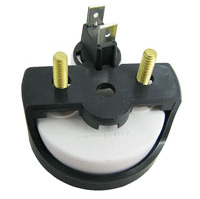
Understanding the Oil Pressure Gauge
|
From the passenger side, left to right in the picture.
The oil pressure sending unit is on the engine block and looks like a small 2 X 3 inch filter with one terminal. There may be another sender plumbed in the same area that has two connectors. It is an oil pressure switch that is supposed to close below 4 psi to activate a dash warning light in some speedometer clusters. To be sure the problem is not the gauge, you can momentarily short the wire from the output of the Sender to ground. If there is no resistance, your gauge should read 80 psi. DO NOT hold it for long in this position. If the needle does not move from zero psi then, either the wiring (open circuit) or the gauge is bad. If it does move, the sender unit is bad. It is very common for the sending units used with the 258 and 232 engines to be inaccurate. Make sure you have a good connection to the sending unit. It is easiest to test the sending unit by temporarily plumbing in a good mechanical gauge.
|
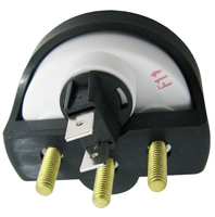
Understanding the Volt Meter Gauge
| From the passenger side, left to right in the picture ... |
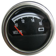
- Volt Meter gauge GND terminal (left) - Black wire (Ground)
- Volt Meter gauge terminal (right) - Red wire (Ignition-on hot 12v)
Testing the voltmeter is easy, you just need a good 12 volt connection to the (+) post and have a good ground to the (-) post. If the gauge shows no activity, then the gauge is bad.
Replacing the gauges is the surest way to eliminate any doubt about whether or not they are working. The low cost of these Jeep parts simply don't justify the time spent analyzing them.