 FREE 1 to 3-Day Delivery on Orders $149+ Details

How to Install a Smittybilt Textured Black XRC Rear Swing Away Tire Carrier on your Wrangler

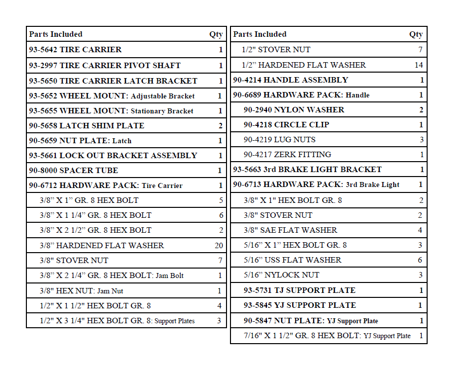
Shop Parts in this Guide
Tire Carrier Installation:
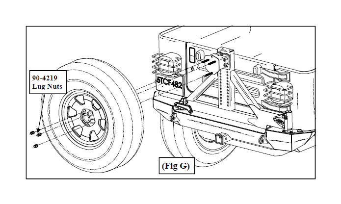
Step 1: Remove the stock spare tire from the vehicle.
Step 2: Unclip the 3rd brake light wiring harness. Unbolt and remove the 3rd brake light housing from the vehicle.
Step 3: Unclip the passenger side taillight housing wiring harness. Unbolt and remove the taillight from the vehicle.
Step 4: Unbolt and remove the tire carrier pivot shaft block off plate.
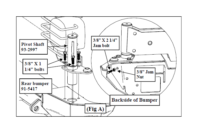
Step 5: Install the pivot shaft (93-2997) to the bumper using the supplied 3/8” X 1 1/4”
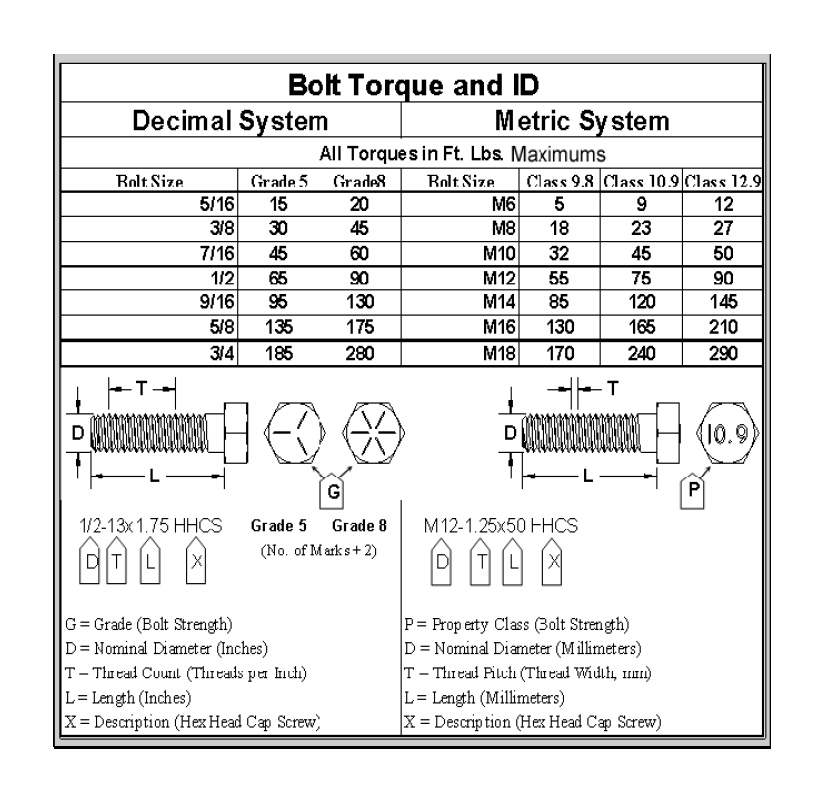
bolts and hardware. (Fig. A) Install the jam nut onto the 3/8” X 2 1/4” jam bolt. Insert the jam bolt assembly into the bumper. (Fig. A) Tighten the jam bolt against the pivot shaft. Tighten the jam nut against the bumper. Torque the bolts according to the chart on page 9.
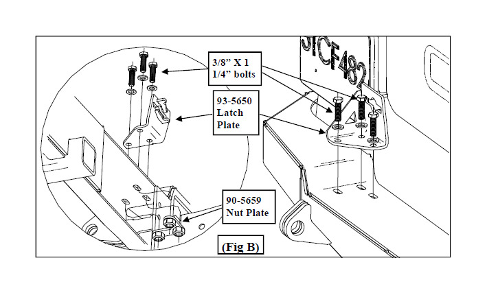
Step 6: Install the latch plate (93-5650) to the bumper using the supplied 3/8” X 1 1/4” bolts and nut plate (90-5659). (Fig. B) Leave the bolts loose at this time. NOTE: The wire on the nut plate may need to be bent in order to properly fish it into place.
Step 7: Place nylon washer onto the pivot shaft, then place tire carrier on top. Be sure to install the tire carrier in the open position. (Fig. C1 & C2)
Step 8: Install the tire carrier lockout mechanism (93-5661) and support plate (93-5731 TJ model only or 93-5845 YJ model only) to the tire carrier (91-5642). Secure using the supplied 1/2” X 3 1/4” pinch bolts, hardware in the (2) pinch bolt holes. For TJ models only: in the remaining support plate hole, insert the 1/2” X 3 1/4” bolt, sleeve (90-8000) and hard-ware in the remaining hole. (Fig. C1). Leave bolts snug only. For YJ models only: in the remaining tire carrier hole, insert the 7/16” X 1 1/2” bolt, nut plate (90-5847 inserted through the upper or lower drain hole in the tire carrier) and 7/16” nut and 1/2” washer. (Fig. C2). Leave bolts snug only.
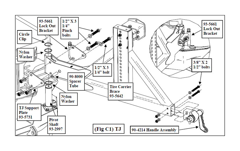
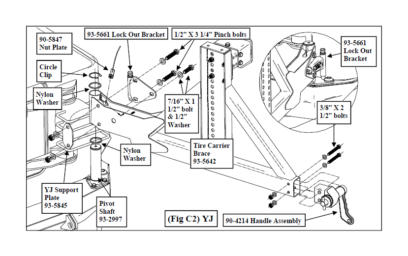
Step 9: Install the handle assembly (90-4214) to the tire carrier using the supplied 3/8” X 2 1/2” bolts. (Fig. C1 & C2) Torque the bolts according to the chart on page 9.
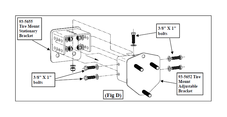
Step 10: Assemble the tire mount bracket (adjustable bracket 93-5652 & stationary
bracket 93-5655) using the supplied (5) 3/8” X 1” bolts and hardware. Leave the bolts
loose at this time. Lay the spare tire face down on the ground and install the tire mount
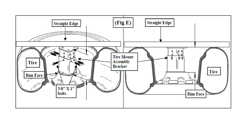
bracket temporarily onto the spare tire. (Fig. D & E)
Step 11: With the spare tire face down, lay a ruler or a flat bar across the tire and adjust the tire mount bracket assembly until the base makes contact with the ruler or flat bar. (Fig. E) Torque the tire mount bracket assembly bolts according to the chart on page 9. NOTE: The assembled bracket may not line up perfectly with the straight edge.
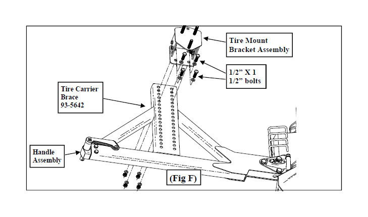
Step 12: Install the tire mount bracket assembly onto the tire carrier using the supplied 1/2” X 1 1/2” hardware. Install the spare tire to the mounting bracket. (Fig. F)
NOTE: The size of the spare tire will determine the mounting height of the bracket. If possible, it is better to have the tire fit tighter against the straight edge/tire carrier to avoid excess vibration.
Step 13: Very carefully close the bumper and watch for tire carrier clearance over top of the bumper. NOTE: Be careful not to scratch the top of the bumper.
Step 14: Adjust the height of the tire carrier by tightening or loosening the (2) 1/2” pinch bolts on the pivot shaft. (Tightening = Higher / Loosening = Lower) Adjust the tire carrier so it swings smoothly and latches correctly. The latch can also be adjusted by inserting the supplied shims (90-5658) as well. Check that the tire carrier lock out mechanism fits properly into the lockout stop on the bumper by carefully swinging it backward. Once the lockout mechanism is aligned properly, tighten the (3) previously installed 1/2” bolts. (Fig. C)
IMPORTANT!: Over-tightening the pinch bolts will not allow the tire carrier to swing freely.
Step 15: Once proper fitment is achieved install the nylon washer and snap ring onto the pivot shaft. Install the Zerk fitting (90-4217) into the top of the pivot shaft (93-2997). (Fig. C) NOTE: Do not over tighten the Zerk fitting.
Step 16: Torque all the tire carrier hardware (except the tire carrier pinch bolts) according to the torque chart on page 9.
Step 17: Reinstall the passenger side taillight using the previously removed OE hardware.
Step 18: Installation of the tire carrier is now complete.
Third Brake Light Installation:
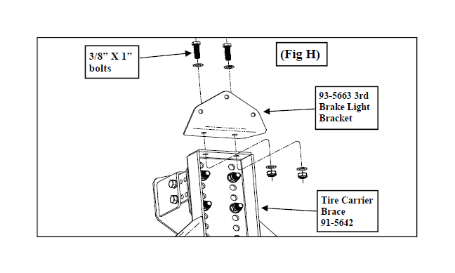
Step 1: Install the 3rd brake light bracket (93-5663) to the top of the tire carrier using the supplied 3/8” X 1” bolts. (Fig. H) Torque the bolts according to the chart on page 9.
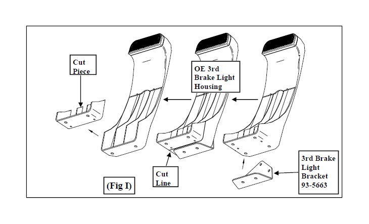
Step 2: Place the OE 3rd brake light plastic housing flush against the back of the 3rd brake light bracket (93-5663). Using the bracket as a guide, scribe a line across the bottom of the plastic light housing. Trim the plastic housing along the scribed line. (Fig. I)
NOTE: Depending on the size of the spare tire, the OE 3rd brake light plastic housing may need additional trimming. Use the spare tire as a guide for any additional trimming.
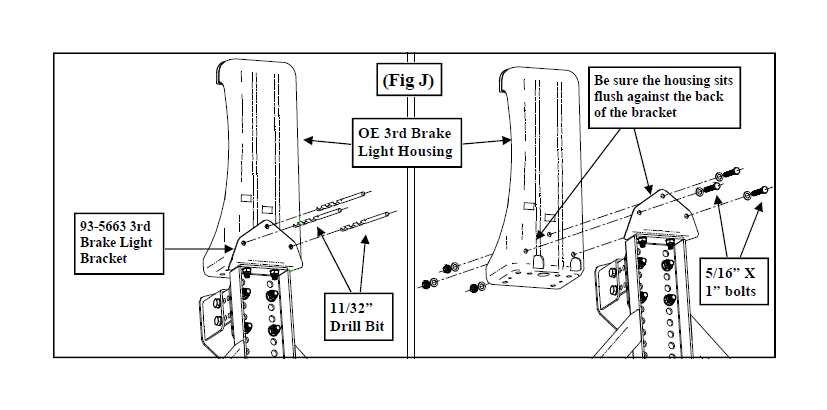
Step 3: Once the OE 3rd brake light plastic housing has been properly trimmed, place it flush against the back 3rd brake light bracket (93-5663). Use the (3) holes in the bracket as a guide to mark and drill the OE brake light plastic housing. Drill the plastic housing using an 11/32” drill bit. (Fig. J) NOTE: The 3rd brake light plastic housing will not sit flush against the bottom of the 3rd brake light bracket (93-5663).
Step 4: Secure the OE plastic housing to the 3rd brake light bracket (93-5663) using the supplied (3) 5/16” X 1” bolts and hardware. (Fig. J)
IMPORTANT!: Do not over tighten these bolts.
Step 5: Reconnect the 3rd brake light wiring harness.
NOTE: It is recommended to extend the 3rd brake light wiring harness. This can simply be done by splicing the wire and using some insulated butt splice connectors and 18 gauge wire, extend the wire to the appropriate length. It is recommended to have this done by an experienced electrical installer.
Step 6: Installation of the third brake light assembly is now complete.
Product cleaning and maintenance instructions
Stainless Steel Finish – Aluminum polish may be used to polish small scratches and scuffs on the finish. Mild soap, window or glass cleaner may be used to clean the finish. Dual state powder coat finish – Mild soap, window or glass cleaner may be used to clean the finish. In order to protect the finish, you may wax your product on a regular basis with pure carnauba automotive wax. Do not use any types of soap, polish or was that contains abrasive that could damage the finish. Textured coated finishes should be cleaned with a mild soap on a damp sponge. Do not apply polish or was that requires to be removed by means of buffing. This type of wax is commonly used at car wash facilities. Chrome Finish – Mild soap, window or glass cleaner may be used to clean the finish. In order to protect the finish you should wax your product on a regular basis with pure carnauba automotive wax. Do not use any types of soap, polish or was that contains abrasive that could damage the finish.

