FREE 1 to 3-Day Delivery on Orders $149+ Details

How to Install a Rough Country 4 in. Lift Kit w/ Shocks on your 2003-2006 Wrangler TJ
Installation Time
1 days
Tools Required
- Spring Compressor
- Silicone spray
- Drill assortment
- Hammer
- Combination wrenches
- Torx key socket
- File
- Floor jacks
- Wheel chocks
- 1/2” drill motor
- Torque wrench
- 1/2 drive ratchet and sockets
- Allen wrenches
- Large “C” clamps and /or bench vise
- Heavy duty jack stands
- Safety glasses
- Anti-seize compound

Shop Parts in this Guide
FRONT INSTALLATION
1. The front-end components are installed first.
2. Place the vehicle on a level surface. Set the parking brake. Center front wheels and chock rear wheels. From inside the engine compartment, remove the upper stud nut, retainer and bushings from both of the front shocks using a 15mm socket.
3. Place jack stands on the frame rail behind the lower control arm mount on the frame and jack up the vehicle. Installation is done one side at a time.
4. Remove the front tires and wheels.
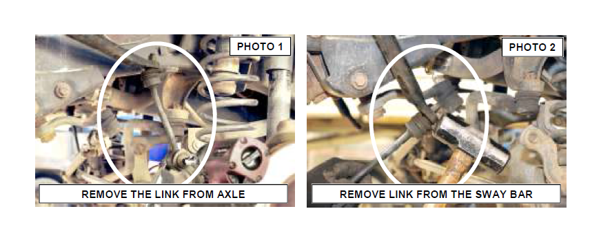
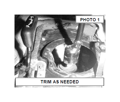
5. Remove both of the front sway bar end links from the axle using a 18mm wrench and the sway bar using a 15mm socket. The upper link can be dislodged by striking the link as shown. See Photo 1 & 2.
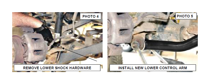
6. Place a floor jack underneath the axle for support and complete the removal of the front shock absorbers using a 13mm socket. See Photo 3. Retain the stock lower hardware for reuse.
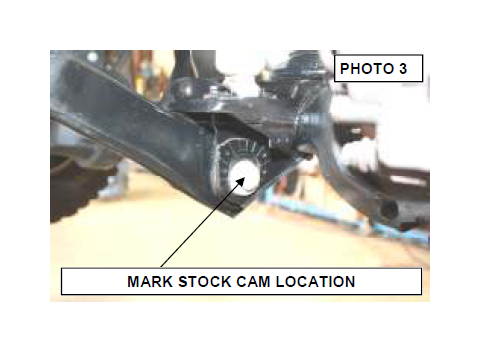
7. Mark the position of the lower control arm cam bolt and axle brackets for installation reference. See Photo 4.
8. If equipped with ABS brakes, remove the sensor wires and clamps for the inside of the lower arms and save clamps for re-use.
9. Remove the track rod bolt from the axle on the passenger side only using a 18mm wrench. It may be necessary to pry bar loose.
10. Remove the coil spring clip located on the bottom coil seat on the driver side of the vehicle using a 13mm socket. Lower the axle and remove the coil spring. A coil spring or strut compressor may be needed to remove the stock coil spring.
11. Remove the stock lower control arm by removing the nut, cam, and cam bolt (if equipped) from the axle bracket and then removing the nut and bolt from the frame bracket using a 21mm socket / wrench, one side at a time.
12. Install the new Rough Country control arm on the frame and axle using factory hardware. See Photo 5. – DO NOT tighten control arm bolts until vehicle is on the ground.
13. If applicable, drill a 23/64” hole into each lower link and reinstall the ABS sensor wires. Use the original clamps.
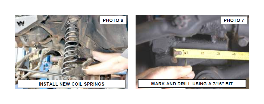
14. A coil spring or strut compressor will be needed for the new coil spring installation. Install the new spring into the upper and lower spring pockets and carefully remove the compressor. Make sure the coil is seated properly in the coil seat by rotating the spring so the pig tail end fits in the spring pocket. See Photo 6.
15. Install the coil spring clamp and torque the spring clip bolt to 16ft.-lbs using a 13mm wrench.
16. Repeat steps on other side.
17. On the front track bar mount. From center of stock track bar hole measure directly over 3/4” and mark using a punch as shown in Photo 7. Drill the new track bar hole using a 7/16” drill bit making sure to keep drill level. Do not reinstall the track rod at this time. This will be preformed in a later step with the vehicle on the ground. Note: This step will not be performed if the optional Adjustable Track Rod was purchased. If installing the optional track
rod, please wait until the vehicle is on the ground to center the front end.
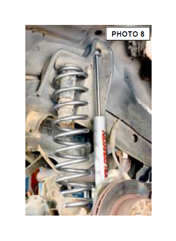
18. Install new front shock absorber part #658693 in the factory lower mount using stock hardware with the body side down. See Photo 8.
19. Install the new upper stud bushings and tighten the upper mounting point only until bushing bulges slightly. Tighten the bar pin on the bottom of the shock with the stock hardware.
20. Repeat this on the opposite side of the vehicle.
21. Install the tires, wheels and lug nuts. Lower the vehicle to the ground and tighten the lug nuts to the factory specifications (80-110 ft. lbs) using crossing pattern..
22. Install the sway bar hoop (u-shaped bracket) on the bottom side of front sway bar where the stock link was secured using the supplied 3/8” x 1.25” bolt, washer, and flanged lock nut. Run bolt from inside to outside.
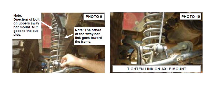
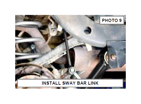
23. Lightly grease and install the 12mm sleeves (larger ID sleeves in bag) provided on the bottom and top of the bent sway bar link. Use the factory hardware to install lower end of link. Place large face washer between bushing and nut. See Photo 9.
24. Install the upper part of the new link in the hoop bracket with the 12mm bolts & flanged nut. See Photo 9 and 10. Note: The bolt must be installed with the nut to outside of vehicle to provide adequate clearance to the frame.
25. Longer brake lines are not required in the front or rear with this kit unless the sway bar is disconnected or this lift is combined with another lift. If disconnects are used, longer brake lines are required and available from Rough Country.
26. Tighten the lower suspension arms to frame bracket. Tighten to 130 ft. lbs. (both sides).
27. Align the reference marks on the adjustment cams and lower arm axle brackets and tighten to 130 ft. lbs.
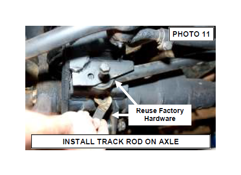
28. Check to be sure the body is centered over the axle. Unlocking the steering wheel and turning the wheel to move the body, do this until the newly drilled track rod extension hole line up. Install the track rod with the stock bolt/flag nut and using a 15mm wrench. See Photo 11. Torque to factory specs.
REAR INSTALLATION
1. Chock the front wheels. Jack up the rear of the vehicle and remove the tires and wheels. Place jack stands on the frame rail to support the vehicle. Place a floor jack under the differential.
2. Remove the stock shock absorbers using a 13mm on the upper mount and a 18mm on the lower mount. Retain the stock hardware for reuse.
3. Remove the stock sway bar links from the frame and the sway bar from the axle using a 15mm socket.
4. On the rear driver side of the vehicle unbolt the track rod from the axle and secure out of the way Retain the factory hardware for reuse.
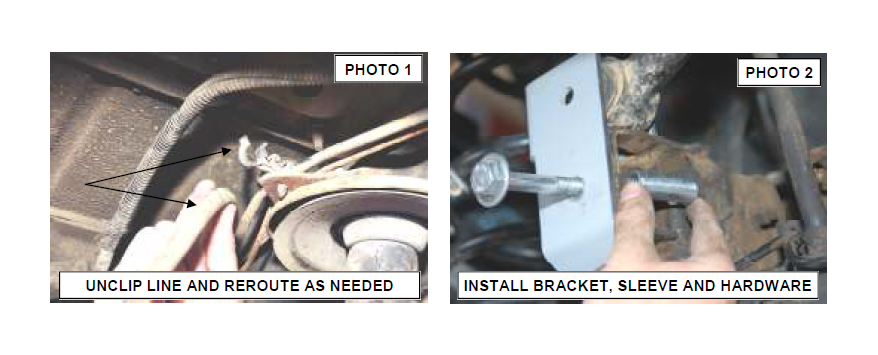
5. Carefully lower the axle with the floor jack and remove the coil springs. NOTE: It may be necessary to use a coil spring or strut compressor to remove the stock coil springs. Take care not to overextend the vent tube on the axle. It may be necessary to unclip the diff vent hose during installation and reroute the hose after installation. See Photo 1.
4. Disconnect the track bar from the axle bracket on driver side of vehicle and install the new track bar relocation bracket in the stock location. Secure using the factory hardware and supplied sleeve as shown in Photo 2.
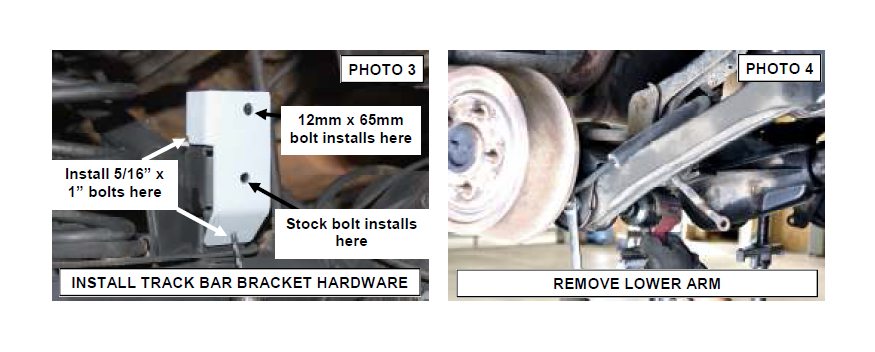
5. Using the bracket hole as a guide and using a 5/16” drill bit, enlarge the 2 holes in the axle mount to accommodate the 5/16” x 1” bolts.
6. Install the 5/16” bolts, washers, lock washers, nuts and tighten. Do not install the track rod in the new bracket at this time. See Photo 3.
7. Remove and replace one suspension arm at a time. Remove the lower arm axle and frame mount bolts using a 21mm socket/ wrench. See Photo 4.
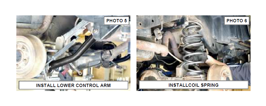
8. Install new lower arm to the frame and axle mount brackets using original hardware. See Photo 5. DO NOT tighten control arm bolts until vehicle is on the ground. If upper adjustable arms or Cam setup have been purchased for upper arms install them at this time. Repeat these steps on the other side.
9. Install the new Rough Country coil springs as shown in Photo 6 making sure the rubber isolator is positioned in the upper mount. It will be necessary to use a coil spring or strut compressor to install the new coil springs.
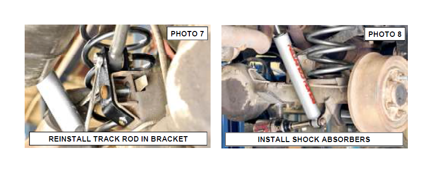
10. Jack up the axle to compress the coil spring and to a align the track rod with the new mounting point and install using a 12mm x 65mm bolt and flange lock nut. See Photo 7.
11. Assemble shock # 658696 with the shock bushings and sleeves. Install the shocks on the vehicle with the factory hardware as shown in Photo 8. Tighten the bar pin on the top of the shock with the stock hardware using a On the lower mount install the supplied washer next to the bushing on its outside face. Note: If the rear sway bars are disconnected a shock relocation bracket will be needed to prevent potential rubbing. This bracket is available from your Rough Country distributor.
12. Reinstall the wheels and tires. Lower the vehicle to the ground and tighten the lug nuts to the factory specifications (80-110 ft. lbs) using crossing pattern.
13. On the rear, slightly grease and insert the sway bar bushings and 10mm sleeves in the new rear extended sway bar links.
14. Secure the links to the stock location, using the 10mm x 60mm bolt, washers and nuts supplied. On the upper mounts you will reuse the factory winged nut. Tighten to 40 ft. lbs using a 15mm socket / wrench. See PHOTO 9.
15. Tighten lower arm pivot bolts to 130 ft. lbs and the rear track bar mounting bolts to 74 ft. lbs.
16. Install transfer case drops or if purchased drive shaft/ SYE combination at this time per the instructions included in packaging.
TRANSFER CASE DROP BRACKET INSTRUCTIONS
1. Place the transmission in neutral, chock wheels, and place floor jack under the transmission mount skid plate.
2. Using a floor jack, support the skid plate.
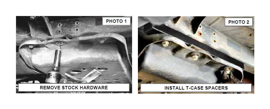
3. Slightly loosen the bolts on the transfer case skid plate on both sides to allow for some movement. Do not remove the bolts. See Photo 1.
4. Proceed to other side. NOTE: Do not attempt to take out the bolts on both sides simultaneously. Installation is done one side at a time. Remove the three bolts holding the transfer case skid plate to the frame rail.
5. Using the floor jack, slightly lower the skid plate and insert the transfer case lowering spacer as shown in Photo 2. (Note the shorter of the two brackets will be installed on the passenger side on the 97-02 models)
6. Using the bolts supplied with the kit slightly tighten the bolts. Do not fully tighten to allow for some movement for the opposite side.
7. Proceed to the opposite side of the vehicle and install the brackets as instructed above. After installing both sides, tighten bolts.
Note: If your vehicle is equipped with a 4 speed automatic and is a 2003-2006 you will have an additional cross member connected to the transfer case by a plate. On this vehicle a total of 2 spacers are used per side. In situations where you are using this vehicle with the front sway bars disconnected (and during full droop during installation) the front drive shaft may hit this cross member.
SHIFT CONTROL BRACKET INSTALLATION
This step is performed only when transfer case drop is used. It is not required if drive shaft/SYE combination is being installed.
1. From underneath the vehicle, locate the shift control bracket. It is attached to the inside of the transmission tunnel on the driver side and acts as a pivot for the transfer case shift lever.
2. Remove the shifter linkage from the shifter plate that is mounted on the body tunnel as shown using a 10 mm wrench. See Photo 1.
3. Reinstall the stock shifter bracket on the new drop bracket as shown with the 1/4” x 3/4” hardware. Tighten using a 7/16” wrench. See Photo 2.
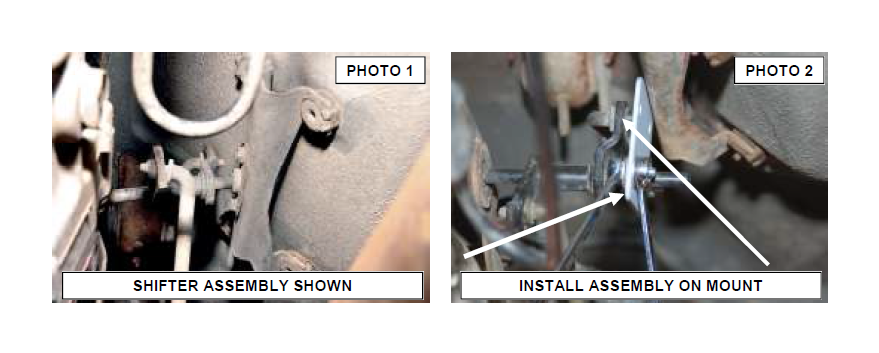
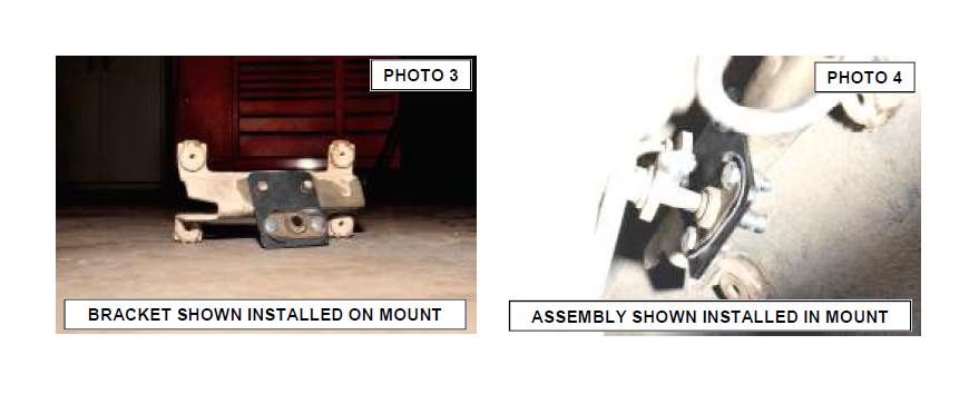
4. Install the supplied drop bracket on the stock tunnel bracket with the supplied 1/4” x 3/4” bolts/washers & nuts. Tighten hardware using a 7/16” wrench. Check clearance on bolts. See Photo 3 & 4. In Photo 3, bracket is shown removed to show mouting location. It is not necessary to remove the bracket although it can be removed to ease installation.
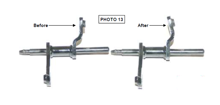
Due to factory variations on the shifter rod bracket, it may be necessary to modify the shifter bracket by slightly bending the mount on the rod to clear the shifter bracket or shifter bracket bolts. After noting how much to bend the bracket to clear, remove the shifter assembly and bend the bracket as shown to slightly clear the bracket / bolts. Do not over-bend!! See Photo 13.
FLOOR PAN MODIFICATION ( MANUAL TRANS ONLY)
This step is only necessary if the vehicle exhibits problems shifting after the lift installation is complete. Test drive the vehicle and shift through all gears. If it is difficult to shift into ( or the transmission jumps out of) Second , Fourth, or Reverse, the shifter may be contacting the edge of the transmission tunnel due to the transfer case drop and might need to be modified slightly. Examine the area and if the shifter is contacting in this area, proceed to the steps below.
If the boot is causing the bind the console can also be relocated or shifted approx 1” and remounted to allow the full shift pattern to be obtained. Only trim if necessary on the tunnel cover.
1. Move the seats to full rearward position.
2. Pry up the shift boot and bezel from the floor console.
3. Remove the bolts attaching the console to the floor pan and lift the console upward and remove.
4. Remove the 4 screws attaching the cover boot to the cover and slide the boot upward to expose the opening in the floor pan.
5. Shift the transmission into 2nd and reverse verifying a minimum of 1/8” clearance between the shifter lever and the floor pan. If necessary, enlarge the opening in the floor pan with a round file See PHOTO 1.
6. Reposition the boot clock wise to match the increased floor pan opening. Mark and drill three new mounting holes. Reinstall the cover boot, console, and shift boot.
7. Reinstall the cover boot, console, and shift boot.
POST INSTALLATION INSTRUCTIONS
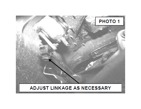
1. Check the transfer case shifter to see if it will move to 4L. If not, the linkage will need adjusting as follows. Place the shifter in 4L, loosen adjustment bolt and push the linkage forward until it stops. Now re-tighten adjustment bolt. Check to be sure 4WD works properly. See PHOTO 1.
2. Check all fasteners for proper torque. Check to ensure for adequate clearance between all rotating, mobile, fixed, and heated members. Verify clearance between exhaust and brake lines, fuel lines, fuel tank, floor boards and wiring harness. Check steering gear for clearance. Test and inspect brake system.
3. Perform steering sweep to ensure front brake hoses have adequate slack and do not contact any rotating, mobile or heated members. Inspect rear brake hoses at full extension for adequate slack. Failure to perform hose check/ replacement may result in component failure. Longer replacement hoses, if needed can be purchased from a local parts supplier.
4. Rotate driveshaft and check for interference at differential yoke and CV joint. If necessary, lightly dress casting(s) and/or U-joint tabs in order to eliminate binding
5. Adjust headlights to proper settings.
6. Have a qualified alignment center realign front end to factory specs. As a general rule you set caster to the minimum of the factory spec and set toe-in to the maximum.
7. Install Warning to Driver decal on sun visor.
8. Grease all control arms and periodically grease as required.
9. Re-torque all nuts and bolts after the first 100 miles, again after another 100 miles and then check periodically thereafter.
10. All components must be retightened after 500 miles, and every three thousand miles after installation