FREE 1 to 3-Day Delivery on Orders $149+ Details

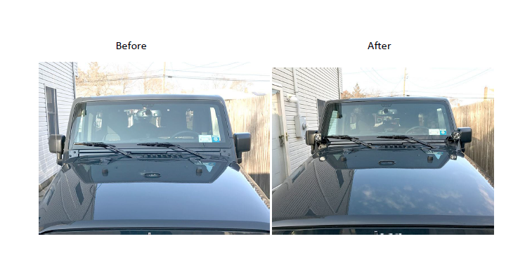
How to Install Vision X Pillar Mounts with Optimus LED Lights and Harness on your Wrangler
Installation Time
30 minutes
Tools Required
- 3/8” Ratchet
- 13mm wrench
- 5mm allen head socket (optional)
- Provided allen key
- T-30 and T-40 sockets

Shop Parts in this Guide
Pre-installation notes: The lighting kit comes equipped with a complete wiring harness for both lights. The harness includes relays and a switch. If you choose to wire the lights directly to an SPOD electrical system, you can cut the positive and negative leads to the relays and wire accordingly. The install guide will explain the routing for wiring from the engine bay through the firewall if you choose to use the provided switch.
Installation Instructions:
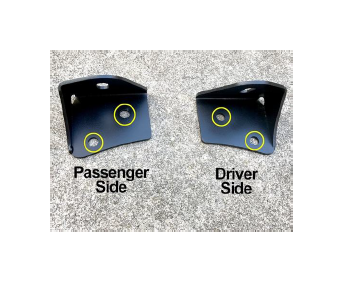
1. Start the installation by first identifying the brackets. The photo details the both the passenger and driver side brackets and highlights the mounting holes
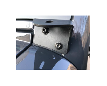
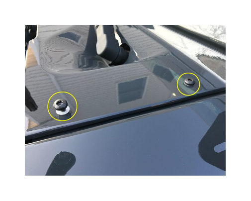
2. Remove the front factory windshield bolts with a T-45 socket on both sides. You can reuse the same factory bolts to attach the lighting bracket, or use the 5mm Allen-head bolts and washers provided with kit.
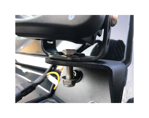
3. Attach both lights to the mount and loosely thread into position with 13mm wrench.
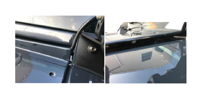
4. Remove the (4) bolts (2 on either side) securing the cowl wiper plate. It’s important to note not to overtighten these screws during reassembly, the metal is then and can indent easily.
5. Connect the light harness to the light’s connection plug on both lights.
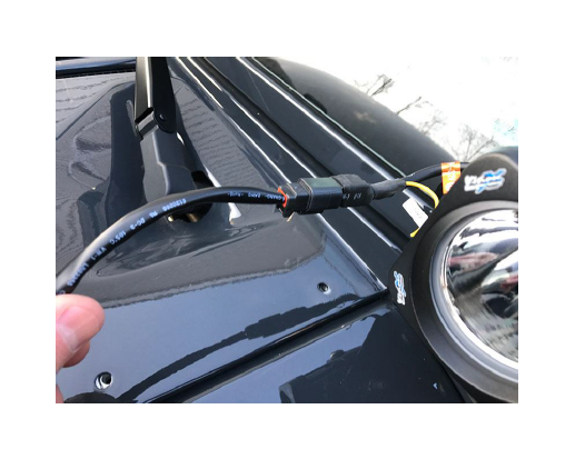
6. Route the wire from the light along the indent in the windshield base and under the wiper cowl. The wiring from the passenger side can be routed within the wiper motor cavity under the cowl plate, towards the driver side.
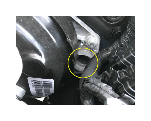
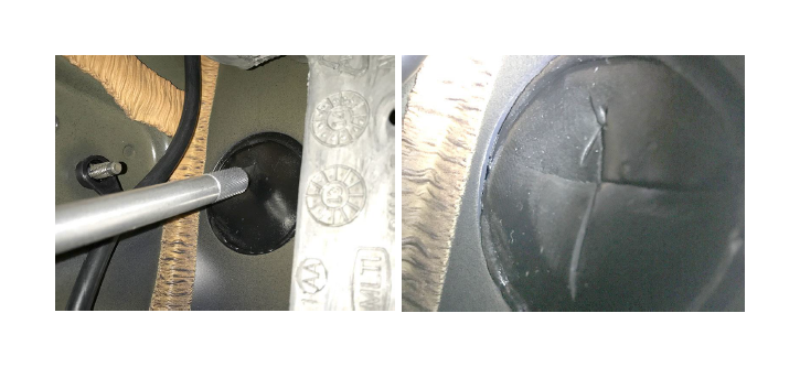
7. Once the wiring has been routed and secured, locate the firewall entry point by the brake booster (highlighted).
8. From inside the jeep, by the pedals on the driver’s side, look to find the back end of the fire wall location, you’ll need to make an X-incision with a blade to feed the wiring through.
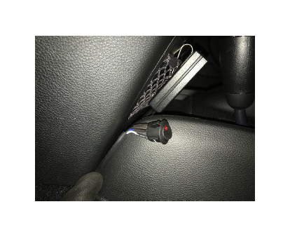
9. Feed the wiring through the new opening and safely route/secure along the inner dash, ensuring that the wires do not come in contact with the pedals. Route the switch to the desire mounting location to finalize the install.
10. Once fully wired and operational. Find a flat area with a wall for final adjustment. Use the provided Allen key for vertical adjustment and the 13mm wrench to adjust the horizontal plane.