 FREE 1 to 3-Day Delivery on Orders $149+ Details

How to Install Tuff Country 4 in. EZ-Flex Off-Road Performance Suspension Lift Kit w/ Shocks (97-06 Wrangler TJ) on your Jeep Wrangler
Front End Installation
1. To begin installation, block the rear tires of the vehicle so that the vehicle is stable and can't roll backwards. Safely lift the front of the vehicle and support the frame with jack stands. Place a jack stands on both the driver and the passenger side. Next remove the wheels and tires from both sides.
2. Working on the driver side, locate the top of the shock absorber stud and remove the nut, retainer washer and grommet. Repeat procedure on passenger side.
Special Note:
Some JEEP TJ's have a variation on the grommet sizes, save the stock grommets, they may need to be re-installed.
3. Using hydraulic floor jacks, support the front axle on the front and passenger side. Next, remove the stock lower shock bolts and nuts and save for later re-installation. (stock shock absrobers can be discard). Longer shocks will be needed with this suspension system. (Shock not included).
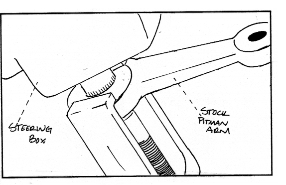
4. Locate the stock pitman arm. Remove the stock cotter pin, castle nut from the tie rod end and the castle nut from the steering box and save hardware for later re-installation. Using a pitman arm puller, remove stock pitman arm and discard. Install new pitman arm into stock location and secure using stock hardware.
See Illustration #1
Illustration #1
5. On the driver side, disconnect the stock way bar end links from the stock axle location and save hardware for later re-installation. Repeat procedure on the passenger side. Next, remove the stock brake lines from the inner frame rail and save hardware for later re- installation.
6. Double check to make sure that the hydrulic jacks are supporting the axle and remove the stock bolt that connects the stick track bar to the stock location on the passenger side axle. Save hardware for later re-installation.
7. Remove the passenger side bolt the connects the stock stabilizer to the stock location and save hardware, if so equipped.
8. On the driver side, locate the stock lower control arm, On the front mounting bracket scribe a mark on the stock alignment cams and reinforcement bracket. This is done for a later installation reference. Repeat procedure on passenger side.
9. On the driver side, remove the stock lower control arm and discard. Save hardware for later re-installation. Repeat procedure on passenger side.
10. On the driver side, remove the stock coil clip and save hardware for later re-installation, if so equipped. Repeat procedure on passenger side.
11. Lower down on both hydraulic floor jacks at the same time. Lower jacks enough that the stock coil can be removed. On the driver side, remove the stock coil spring and discard. Repeat procedure on passnger side.
12. Locate a new front coil springs, on the driver side, install the new coil spring into stock location. Repeat procedure on passenger side.
13. On the driver side, re-install the stock coil spring clip with stock hardware, if so equipped. Repeat procedure on passenger side.
14. Raise up on the hydraulic floor jacks until the new coil springs seat properly into stock location.
Special note :Make sure the rubber spring isolator is flush with the upper stock frame bracket on each side
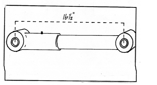
15. Locate the (2) new front lower EZ flex control arms.
Special Note: Before installation of new EZ flex arms, make sure the center of eyelet measurement, is measurement at 16.5" long.
See Illustration #2
Illustration #2
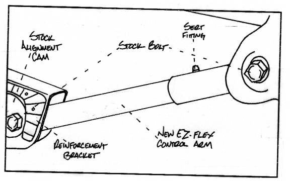
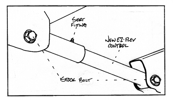
16. On the driver side, install the new EZ flex lower control arm into the rear mount and secure using stock hardware. Do not fully tighten at this point. Insert the front of the control arm into the front bracket.
Special note: Make sure that when you install the new EZ flex arm that the sert fitting is pointing upwards. Slight prying of the stock control arm mounts may be needed to make installation easier. Also raising the axle to ride height and moving it slightly up and down will make for easier installation. Now re-install the stock cam bolt and nut. Refer to the reference mark that was make in step #8 and re-bolt into the stock location.
Special note: Torque both the front and rear mount to 90 ft. lbs. Repeat procedure on passenger side.
See Illustration # 3
Illustration # 3
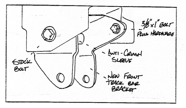
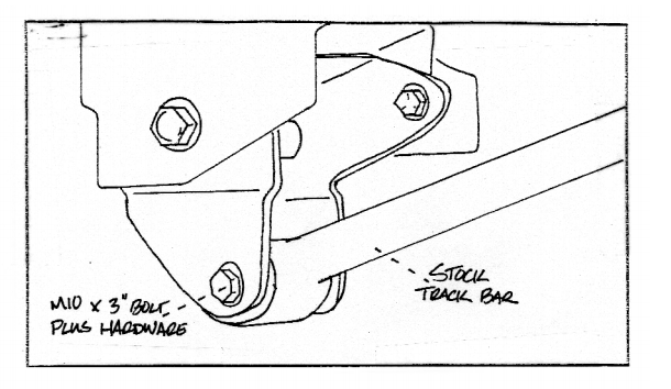
17. Locate the new track bar relocating bracket, (1) 10 mm x 3" bolt, (1) 10 mm lock nut, (1) 3/8" x 1" bolt, (1) 3/8" unitorque nut, (4) 3/8" flat washers and (1) 15.204 track bar anti crush sleeve. Install new track bar relocation bracket into passenger side stock track bar location with the open end down, Install new spacer sleeve into the upper hole of new track bar bracket. Secure using stock hardware. Do not fully tighten at this point. Make sure that the newly installed track bar relocation bracket is level use the new bracket as guide and drill a 3/8" hole into the back side of stock track bar bracket. Secure using new 3/8" hardware and torque to 32 ft. lbs
See Illustration # 4
Illustration # 4
18. Install the stock track bar into newly track bar bracket and secure using (1) 10 mm x 3" bolt, (1) 10mm lock nut and (2) 3/8" flat washers. Torque to 45 ft lbs. If your are not able to lineup the hole in the stock track bar and the new track bar bracket, the weight of the vehicle may need to be on the ground, if this is the case perform this step after installation step #22.
See Illustration # 5
Illustration # 5
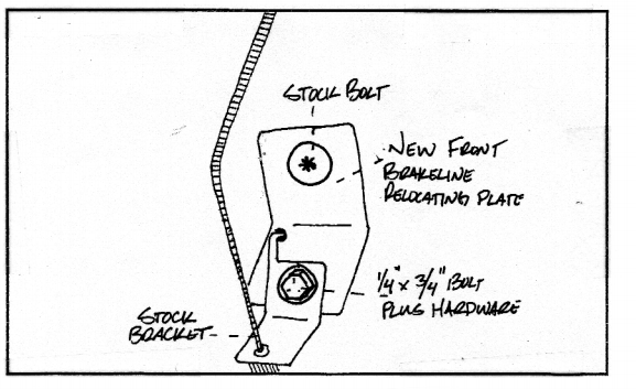
19. Locate (2) new front brakeline extensions, (2) 1/4" x 3/4:" bolts, (2) 1/4" flat washers. On the driver side, install new brakeline bracket to inner frame rail. Secure using stock hardware. Install stock brakeline bracket and secure using 1/4" hardware. Torque to 15 ft lbs. Repeat procedure on passenger side.
See Illustration # 6
Illustration # 6
20. Longer shock will be needed with this suspension kit. Tuff Country recommends a 23" fully extended hydraulic shock. In the poly bag with your instruction sheet, locate the shock bar pins. Install the new bar pin into each shocks lower eyelet. Install the shock dust boot cover on both shocks. On the lower stock location and secure using lower shock mount into the stock location and secure using new grommets and 3/8" nut.
Special note: Stock grommets may need to be re-installed of new grommets are too small.
21. Re-install the stock stabilizer into the stock location and secure using stock hardware.
22. Re-install the stock sway bar end links into stock location and secure using stock hardware.
Special Note: If the end links are not able to reconnect the weight of the vehicle have to be on the ground.
Check and double check to make sure that all installation steps were performed properly and that all hardware is torqued to proper specifications. Mount wheels and tire and safely lower vehicle to the ground.
If you were unable to line up the stock track bar and new track bar bracket from Step # 18 at this time.
Front end Installation complete.
Rear End Installation
23. Block the front tires of the vehicle so that the vehicle is stable and can't roll forward. Safely lift the rear of the vehicle and support the frame with jack stands. Place the jack stands on both the driver and the passenger side. Next remove the wheels and tires from both sides.
24. Position hydraulic floor jacks under both the driver and passenger side rear exle. Raise up on both floor jacks until contact is made on the axle.
25. On the driver side, remove the stock sway bar end link from the stock location and discard the stock end link. New end links are provided in this suspension system. Save stock hardware and repeat procedure on passenger side.
26. Remove both rear shock absorbers and discard. Save stock hardware for later re-installation. Longer shocks will be needed with the suspension system. (Shock not included).
27. On the driver side, remove the stock bolt that connects the stock track bar to the stock location and save hardware for later re- installation.
Special note: Remove the stock plastic cover that overlaps the stock rear trak bar bracket and discard.
28. On the driver side, remove the stock lower control arm and discard. Save hardware for later re-installation. Repeat procedure on passenger side.
29. On the driver side, remove the stock coil clip and save hardware for later re-installation. If so equipped. Repeat procedure on passenger side.
30. Lower down on both hydraulic floor jacks at the same time. Lower jacks enough that the stock coil springs can be removed. On the driver side, remove the stock coil spring and discard. Repeat procedure on passenger side.
31. Locate the new rear coil springs, on the driver side install the new coils spring into stock location.Repeat procedure on the passenger side.
32. On the driver side, re-install the stock coil spring clip with the stock hardware. If so equipped. Repeat procedure on passenger side.
33. Raise up on the hydraulic floor jacks until the new coil springs seat properly into stock location.
Note: Make sure the rubber spring isolator is flush with the upper stock frame brackets on each side.
34. Locate the (2) new rear lower EZ flex control arms.
Special note: Before installation of new EZ flex arms, make sure that the center of eyelet measurement, is measuring at 16.5" long.
See illustration # 2
35. On the driver side, install new EZ flex lower control arm into the front mount and secure using stock hardware. Do not fully tighten at this point. Insert the rear of the lower control arminto the rear bracket.
Special Note: make sure that when you install the new EZ flex arm that the sert fitting is pointing upwards. Slight prying of the stock control arm mounts may be needed to make.
See Illustration # 7
Illustration # 7
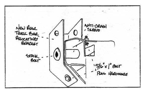
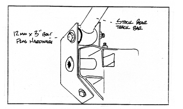
36. Locate the new rear track bar bracker, (1) 12 mm x 3" bolt, (1) 12 mm lock nuts, (2) 5/16" unitorque nuts, (4) 5/16" flat washers (2) 7/16" flat washers and (1) rear track bar anti crush sleeve. Install the new rear track bar bracket over the stock track bar bracket and secure using stock hardware and new anti crush sleeve into stock location. Torque to 75 ft lbs. Using the new bracket as a guide, drill a 5/16" hole in the bottom and the top of the stock track bar bracket. Secure using 5/16" x 1" bolt and hardware. Torque to 18ft lbs.
See Illustration # 8
Illustration # 8
37. Install the stock track bar into newly installed track bar bracket and secure using (1) 12 mm x 3" bolt, (1) 12 mm lock nut and (2) 7/16" flat washers. Torque to 45 ft lbs. If you are not able to line up the hole in the stock track bar and the new track bar bracket, the weight of the vehicle may need to be on the ground, if this is the case perform this step after installation step # 40.
See Illustration # 9
Illustration # 9
38. Locate (2) new rear sway bar end links, (4) sway bar end link bushins and (4) rear sway bar end link sleeves. Install new bushing and sleeves into each end of the new sway bar end links.
Special Note: Use a lithium or moly base grease prior to inserting bushing into the new sway bar end links. This will increase the life of the bushings as well as prevent squeaking.
On the driver side install the new sway bar end link into the stock location and secure using stock hardware.
Torque to 85 ft lbs. Repeat procedure on the passenger side.
39. Longer shock will be needed with this suspension kit. Tuff country recommends a 26" fully extended hyraulic shock. Install the shock dust boot cover on both shocks. In the poly bag with your instruction sheet locate the bar pins. Install the new bar pin into each stocks upper eyelet. On the driver side, install the new shock into the upper stock location and secure using upper shock mounting hardware. Install the lower shock mount into the stock location and secure using stock hardware.
40. Check and double check to make sure that all steps were performed properly. re-install the tire and wheels and safely lower the vehicle to the ground.
If you were unable to line up the stock track bar and new track bar bracket from step # 37. Perform Step # 37 at this time.
Rear End Installation complete.
TRANSFER CASE LOWERING KIT
Before beggining these steps: Make sure vehicle is on a flat and level surface, block the front and rear tires and place transmission in neutral.
41. Place a jack stand under the transfer case crossmember and remove the six stock bolts that secures the stock transfer case skid plate to the frame. (Three on each side of the skid plate.) Stock bolts may be discarded. Ease down on jack so that the skid plate lowers about 2".
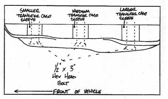
42. Locate (6) transfer case sleeves (Three different sizes) and (6) 1/2" x 3" hex head bolts. Install the new transfer case sleeves between the transfer case cross member and frame. Three per side..
Special Note: There are three different size sleeves. The longer sleeves will go towards the rear of the vehicle, the middle sleeves will go towards he front of the vehicle.
Secure trasfer case cross member to frame using the 1/2" x 3" hex head bolts and torque to 85 ft lbs. Make sure to use lock tight on the new transfer case bolts and Tuff Country highly recommended that a air ratchet is used. If a air gun used the new bolts may strip.
See Illustration # 10
Illustration # 10
Translation Case Lowering Kit Installation Complete
Check and double check to make sure all steps were performed properly and take directly to an alignment center for proper alignment.
