FREE 1 to 3-Day Delivery on Orders $149+ Details

How to Install Tuff Country 2" Suspension Lift Kit on your 1997-2006 Wrangler
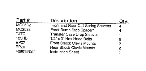
PARTS LIST:
Congratulations on your selection to purchase a Tuff Country EZ-Ride Suspension System. We at Tuff Country are proud to offer a high quality product at the industries most competitive pricing. Thank you for your confidence in us, and our product.
Before installation begins, it is the customers/installers responsibility to make sure that all parts are on hand. If any parts are missing, please feel free to call one of our customer service representative @ (800) 288-2190.
Make sure to use locktite on all new and stock hardware associated with this installation.
Product safety label must be installed inside the cab in plain view of all occupants.
It is the responsibility of the installers to make sure that the rear view mirror hanger is hung from the rear view mirror. The rear view mirror hanger has instructions on proper post installation procedures.
Tuff Country EZ-Ride Suspension highly recommends that a qualified and or certified mechanic performs this installation.
If you desire to return your vehicle to stock, it is the customers responsibility to save all stock hardware.
IMPORTANT CUSTOMER INFORMATION
This vehicles reaction and handling characteristics may differ from standard cars and/or trucks. Modifications to improve and/or enhance off road performance may raise the intended center of gravity. Extreme caution must be utilized when encountering driving conditions which may cause vehicle imbalance or loss of control. DRIVE SAFELY! Avoid abrupt maneuvers, such as sudden sharp turns which could cause a roll over, resulting in serious injury or death.
It is the customers responsibility to make sure that a re-torque is performed on all hardware associated with this suspension system after the first 100 miles of installation. It is also the customers responsibility to do a complete re-torque after every 3000 miles or after every off road use.
After the original installation, Tuff Country EZ-Ride Suspension also recommends having the alignment check every 6 months to ensure proper tracking, proper wear on tires and front end components. Tuff Country EZ-Ride Suspension take no responsibility for abuse, improper installation or improper suspension maintenance.
It is the responsibility of the customer or the mechanic to wear safety glasses at all times when performing this installation.
It is the customers/installers responsibility to read and understand all steps before installation begins. OEM manual should be used as a reference guide.
The Tuff Country EZ-Ride Suspension product safety label -that is included in your kit box must be installed inside the cab in plain view of all occupants.
LIMITED LIFETIME WARRANTY
Notice to all Tuff Country EZ-Ride Suspension customers: It is your responsibility to keep your original sales receipt! If failure should occur on any Tuff Country EZ-Ride Suspension component, your original sales receipt must accompany the warranted unit to receive warranty. Warranty will be void if the customer can not provide the original sales receipt. Do not install a body lift in conjunction with a suspension system. If a body lift is used in conjunction with any Tuff Country EZ-Ride Suspension product, your Tuff Country EZ-Ride Suspension WARRANTY WILL BE VOID. Tuff Country Inc. ("Tuff Country" ) suspension products are warranted to be free from defects in material and workmanship for life if purchased, installed and maintained on a non-commercial vehicle; otherwise, for a period of twelve (12) months, from the date of purchase and installation on a commercial vehicle, or twelve thousand (12,000) miles (which ever occurs first). Tuff Country does not warranty or make any representations concerning Tuff Country Products when not installed and used strictly in accordance with the manufacturer's instructions for such installation and operation and accordance with good installation and maintenance practices of the automotive industry. This warranty does not apply to the cosmetic finish of Tuff Country products nor to Tuff Country products which have been altered, improperly installed, maintained, used or repaired, or damaged by accident, negligence, misuse or racing. ("Racing is used in its broadest sense, and, for example, without regards to formalities in relation to prizes, competition, etc.) This warranty is void if the product is removed from the original vehicle and re-installed on that or any other vehicle. This warranty is exclusive and is in lieu of any implied warranty of merchantability, fitness for a particular purpose or other warranty of quality, whether express or implied, except the warranty of title. All implied warranties are limited to the duration of this warranty. The remedies set forth in this warranty are exclusive. This warranty excludes all labor charges or other incidental of consequential damages. Any part or product returned for warranty claim must be returned through the dealer of the distributor from whom it was purchased. Tuff Country reserves the right to examine all parts returned to it for warranty claim to determine whether or not any such part has failed because of defect in material or workmanship. The obligation of Tuff Country under this warranty shall be limited to repairing, replacing or crediting, at its option, any part or product found to be so defective. Regardless of whether any part is repaired, replaced or credited under this warranty, shipping and/or transportation charges on the return of such product must be prepaid by the customer under this warranty.
Please Follow Instruction Carefully
Before installation begins, drive and check to make sure there are no uncommon sounds and or frame damage. Also at this time measure from the center of the hub to the bottom of the fender well and record measurements below.
Pre Installation Measurements:
Driver Side Front: ______________________________________________
Passenger Side Front: __________________________________________
Driver Side Rear: ______________________________________________
Passenger Side Rear: ___________________________________________
At the end of the installation take the same measurements and compare to the pre-installation measurements.
Post Installation Measurements:
Driver Side Front: ______________________________________________
Passenger Side Front: __________________________________________
Driver Side Rear: ______________________________________________
Passenger Side Rear: ___________________________________________
Please follow instructions carefully:
Front End Installation:
1. To begin installation, block the rear tires of the vehicle so that the vehicle is stable and can't roll backwards. Safely lift the front of the vehicle and support the frame with jack stands. Place a jack stand on both the driver and passenger side. Next remove the wheels and tires from both sides.
2. Place a hydraulic floor jack on both the driver and passenger side of the front differential. Raise up on both hydraulic jack stands at the same time until they make contact with the front differential.
3. Working on the driver side, remove the stock front sway bar end link from the stock front axle and save hardware for later re-installation. Repeat procedure on passenger side.
4. Working on the driver side, remove the stock front shock from the stock location and save mounting hardware for late re-installation. Longer shocks will be needed, the stock shocks may be discarded. Repeat procedure on passenger side.
5. Working on the passenger side, remove the stock track bar from the stock axle location and save hardware for later re-installation.
6. Working on the driver side, remove the stock lower control arm from the stock frame location_ and_save hardware for later re-installation. Repeat procedure on passenger side.
7. Carefully lower down on both hydraulic floor jacks at the same time approximately 3". This will allow enough room for the stock coil springs to be removed. Special Note: Make sure that the stock brake lines do not over extend.
8. Working on the driver side, remove the stock coil spring retaining clip from the stock location and save clip and hardware for later re-installation. (If so equipped) Repeat procedure on passenger side.
9. Working on the driver side, remove the stock coil spring and set aside for later re-installation. Repeat procedure on passenger side.
10. Working on the driver side, remove the stock front bump stop and discard. Repeat procedure on passenger side.
11. Working on the driver side, remove the stock front bump stop cup and save hardware for later re-installation. Repeat procedure on passenger side.
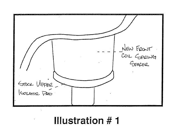
12. Locate (2) front coil spring spacers. Working on the driver side, install the front coil spring spacer into the stock front coil spring pocket. Special Note: To make installation easier, use a lithium or moly base grease to help the new spacer slide up into the stock pocket. Also make sure that stock upper isolator pad is installed on the bottom of the coil spring spacer. Repeat procedure on passenger side.
See Illustration # 1
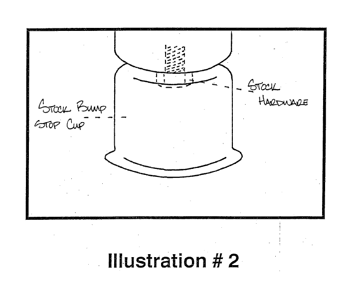
13. Working on the driver side, re-install the stock bump stop cup using the stock hardware that was removed in step # 11. Repeat procedure on passenger side.
See Illustration # 2
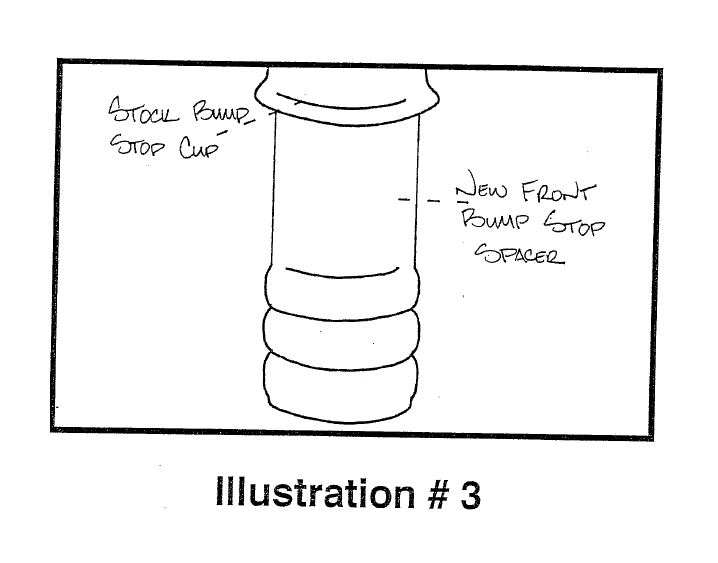
14. Locate (2) new front bump stop spacers. Working on the driver side, install the front bump stop spacer into the stock bump stop cup. Special Note: To make installation easier, use a lithium or moly base grease to help the new bump stop spacer slide up into the stock pocket. Repeat procedure on passenger side.
See Illustration # 3
15. Working on the driver side, re-install the stock coil spring that was removed in step # 9. Repeat procedure on passenger side.
16. Working on the driver side, re-install the stock coil spring retaining clip that was removed in step # 8. (If so equipped) Repeat procedure on passenger side.
17. On the driver side, re-install the stock lower control into the stock frame location and secure using the stock hardware that was removed in step # 6. Torque to 85 ft. lbs. Special Note: Slight prying of the stock lower control arm mounts may be needed to make installation easier. Also raising the axle to ride height and moving it slightly up and down will make for easier installation. Repeat procedure on passenger side.
18. Working on the driver side, re-install the stock front track bar into the stock front track bar bracket and secure using the stock hardware that was removed from step # 5. Torque to 30 ft. lbs. Special Note: If you are not able to line up the hole in the stock track bar and the stock track bar bracket, the weight of the vehicle may need to be on the ground. If this is the case perform this step, once the weight of the vehicle is on the ground.
19. Longer shocks will be needed with this suspension system. Tuff Country EZ-Ride Suspension recommends using a 20" fully extended, hydraulic shock.
20. Working on the driver side, install the new shock into the stock location and secure using the stock hardware that was removed from step # 4. Repeat procedure on the passenger side.
21. Working on the driver side, re-install the stock sway bar end link to the stock axle location and secure using the stock hardware that was removed from step # 3. Repeat procedure on passenger side. Special Note: If you are not able to re-install the stock sway bar end link to the stock sway bar, the weight of the vehicle may need to be on the ground. If this is the case perform this step, once the weight of the vehicle is on the ground.
22. Carefully remove both hydraulic floor jacks. Install the tires and wheels and safely lower the vehicle to the ground.
23. If you were not able to perform step # 18 & # 21, perform these steps at this point..
24. Check and double check to make sure that all steps associated with the front end suspension system were performed properly.
Front End Installation Complete:
Rear End Installation:
25. To begin installation, block the front tires of the vehicle so that the vehicle is stable and can't roll forward. Safely lift the rear of the vehicle and support the frame with jack stands. Place a jack stand on both the driver and passenger side. Next remove the wheels and tires from both sides.
26. Place a hydraulic floor jack on both the driver and passenger side of the rear differential. Raise up on both hydraulic jack stands at the same time until they make contact with the front differential.
27. Working on the driver side, remove the stock rear sway bar end link from the stock sway bar location and save hardware for later re-installation. Repeat procedure on passenger side.
28. Working on the driver side, remove the stock rear shock from the stock location and save mounting hardware for late re-installation. Longer shocks will be needed, the stock shocks may be discarded. Repeat procedure on passenger side.
29. Working on the passenger side, remove the stock track bar from the stock frame location and save hardware for later re-installation.
30. Working on the driver side, remove the stock lower control arm from the stock frame location and save hardware for later re-installation. Repeat procedure on passenger side.
31. Carefully lower down on both hydraulic floor jacks at the same time approximately 3". This will allow enough room for the stock coil springs to be removed. Special Note: Make sure that the stock brake lines do not over extend.
32. Working on the driver side, remove the stock coil spring retaining clip from the stock location and save clip and hardware for later re-installation. (If so equipped) Repeat procedure on passenger side.
33. Working on the driver side, remove the stock coil spring and set aside for later re-installation. Repeat procedure on passenger side.
34. Working on the driVer side, remove the stock rear bump stop and discard. Repeat procedure on passenger side.
35. Working on the driver side, remove the stock rear bump stop cup and save hardware for later re-installation, Repeat procedure on passenger side.
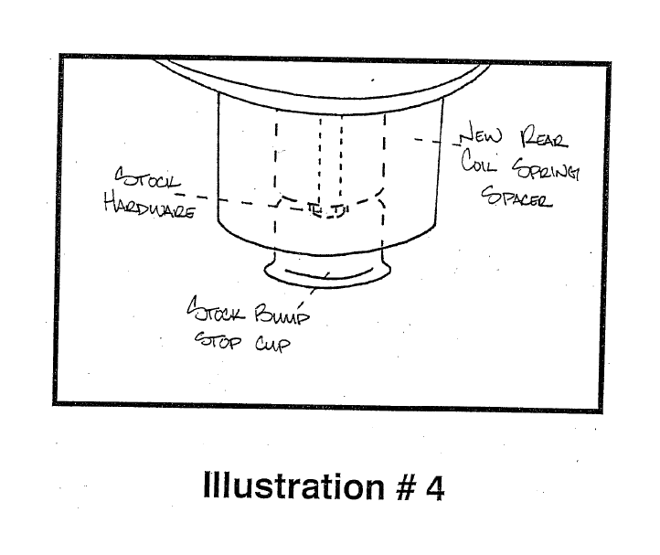
36. Locate (2) new rear coil spring spacers. Carefully press in the stock rear bump stop cup that was removed from step # 35. Working on the driver side, install the rear coil spring spacer into the upper stock coil spring pocket using stock hardware for the stock bump stop cup. Repeat procedure on passenger side.
See Illustration # 4
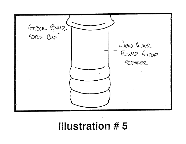
37. Locate (2) new rear bump stop spacers. Working on the driver side, install the rear bump stop spacer into the stock bump stop cup. Special Note: To make installation easier, use a lithium or moly base grease to help the new bump stop spacer slide up into the stock pocket. Repeat procedure on passenger side.
See Illustration # 5
38. Working on the driver side, re-install the stock coil spring that was removed in step # 33. Repeat procedure on passenger side.
39. Working on the driver side, re-install the stock coil spring retaining clip that was removed in step # 32. (If so equipped) Repeat procedure on passenger side.
40. On the driver side, re-install the stock lower control into the stock frame location and secure using the stock hardware that was removed in step # 30. Torque to 85 ft. lbs. Special Note: Slight prying of the stock lower control arm mounts may be needed to make installation easier. Also raising the axle to ride height and moving it slightly up and down will make for easier installation. Repeat procedure on passenger side.
41. Working on the driver side, re-install the stock rear track bar into the stock frame rear track bar bracket and secure using the stock hardware that was removed from step # 29. Torque to 30 ft. lbs. Special Note: If you are not able to line up the hole in the stock track bar and the stock track bar bracket, the weight of the vehicle may need to be on the ground. If this is the case perform this step, once the weight of the vehicle is on the ground.
42. Longer shocks will be needed with this suspension system. Tuff Country EZ-Ride Suspension recommends using a 23" fully extended hydraulic shock.
43. Working on the driver side, install the new shock into the stock location and secure using the stock hardware that was removed from step # 28. Repeat procedure on the passenger side.
44. Working on the driver side, re-install the stock sway bar end link to the stock location and secure using the stock hardware that was removed from step # 27. Repeat procedure on passenger side. Special Note: If you are not able to re-install the stock sway bar end link to the stock sway bar, the weight of the vehicle may need to be on the ground. If this is the case perform this step, once the weight of the vehicle is on the ground.
45. Carefully remove both hydraulic floor jacks. Install the tires and wheels and safely lower the vehicle to the ground.
46. If you were not able to perform step # 41 & # 44, perform these steps at this point.
47. Check and double check to make sure that all steps associated with the rear end suspension system were performed properly.
Rear End Installation Complete: —
Transfer Case Lower Kit
Before beginning these steps, make sure that the vehicle is on a flat level surface, block the front and rear tires and place the transmission in neutral.
48. Place a hydraulic jack stand under the transfer case cross member and raise up until the hydraulic jack makes contact with the transfer case cross member.
49. Working on the driver side, remove the (3) stock bolts that hold the transfer case cross member to the frame. New bolts will be used, the stock bolts may be discarded. Repeat procedure on passenger side.
50. Carefully lower down on the hydraulic floor jack so that the transfer case cross member lowers about 2"
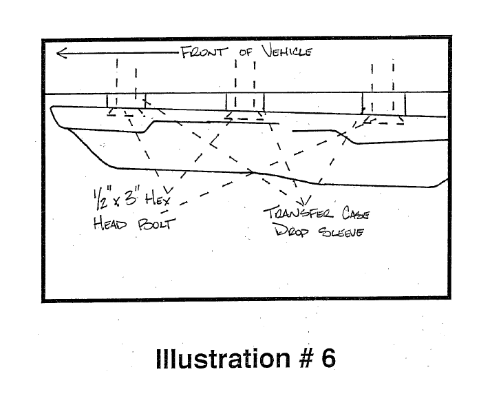
51. Locate (6) transfer case sleeves, (three different sizes) and (6) 1/2" x 3" hex head bolts. Working on the driver side, install the new transfer case drop sleeves between the transfer case cross member and the frame. (3) per side. Special Note: There are three different sizes of sleeves, the longer sleeve will go towards the rear of the vehicle, the middle size sleeve will go in the middle location and the smaller sleeve will go towards the front of the vehicle. Secure the transfer case cross member to the frame using the new 1/2" x 3" hex head bolts and torque to 85 ft. lbs. Special Note: Make sure to use locktite on the new transfer case bolts. Also Tuff Country does not recommend using a air gun on these bolts, if an air gun is used the new bolts may strip. Repeat procedure on passenger side.
See Illustration # 6
52. Safely remove the hydraulic floor jack from under the vehicle.
Transfer Case Lower kit Installation Complete
Check and double to check to make sure that all steps associated with this suspension system were performed properly and take directly to an alignment shop.
Congratulations Installation Complete
Important Notice: It is the installers responsibility to make sure that the caution decal is installed on the rear view mirror. This will allow the owner of the vehicle to understand the proper post installation procedure. Also it is the installer responsibility to make sure that the owner of the vehicle receives a copy of the installation manual.