FREE 1 to 3-Day Delivery on Orders $149+ Details

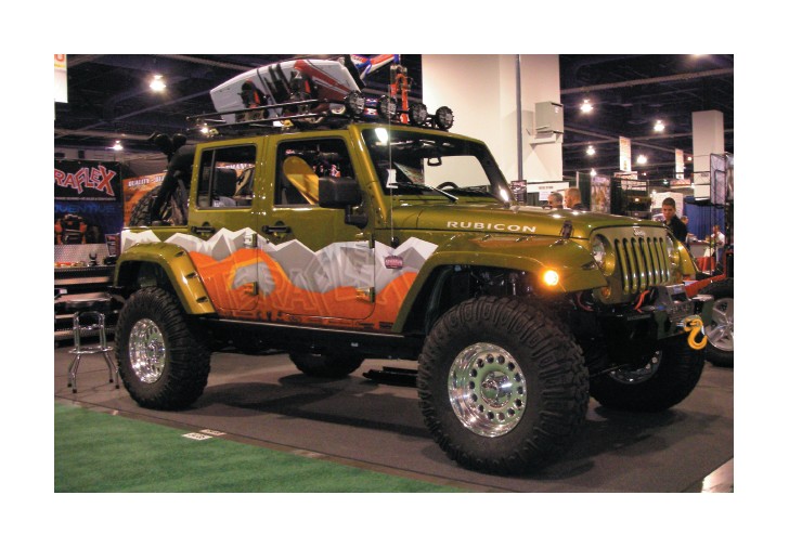
How to Install Teraflex 4 in. Lift Kit w/ Flex Arms w/o Shocks on your Wrangler
Attention: Driveshaft modification may be required following installation of any suspension lift on the JK Wrangler. Read the notes at the end of this installation guide for more information.
Keep this a safe operation by properly supporting the vehicle during installation of the TeraFlex suspension lift kit.
Kit includes:
New 4-inch coil springs
Front sway bar link kit
Rear sway bar links
Shock absorbers
Front upper bump stop extensions
Front lower bump stops
Rear upper bump stop extensions
Rear lower bump stops
Front spring spacers
Rear spring spacer/guides
Rear trackbar bracket
Front adjustable track bar
Front upper FlexArms
Front lower FlexArms
Rear upper FlexArms
Rear lower FlexArms
Rear brake lines
Front brake lines
Rear spring retainers
Hardware kit
1. Lift the vehicle and support under the frame so that the axles will be able to drop down far enough to remove and replace the coil springs.
2. Remove the tires.
3. Support the rear axle and remove the rear shocks.
4. Remove the rear sway bar links.
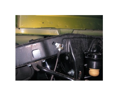
5. Remove the clips that secure the ABS wiring harness to the upper control arm mount.
6. Replace the rear factory brake hoses with the new longer brake hoses.
7. Remove the bracket that holds the park brake cables to the body.
8. Unbolt the frame end of the rear track bar. Set aside bolts for use later.
9. Carefully lower the rear axle far enough to remove the rear coils. Hold on to the coils so they don’t just fall out as you lower the axle.
10. Working on one side at a time replace the lower, then the upper factory control arms with the new FlexArms, then repeat on the other side.
Note: Each rear upper FlexArm has a sticker to identify and locate the arm. Install the arm so that the sticker faces up. Adjust the length to 18-3/8”. Final length will be set on the alignment rack.
Set the length of the rear lower arm to 20-3/8”. Install the rubber bushing end to the frame bracket. Final length adjustment will be made on the alignment rack. Do not fully torque the control arm bolts until the vehicle is sitting on the ground with the arms at ride height to avoid pre-stressing the rubber bushings.
11. After removing the stock springs allow the axle to drop a little bit more to make room to install the new 4-inch rear coil springs. Watch the axle breather hose, the brake lines and ABS wiring to make sure they are not supporting the weight of the rear axle.
12. Before installing the new rear springs, install the rear coil spring guide and spacer by pushing it into the hole in the frame directly above the rear coil spring. Putting some grease on the top spacer button will help the spacer pop into place.
13. If you plan to carry a lot of weight in the rear of the vehicle, reinstall the factory spring isolator onto the TeraFlex spring spacer/guide, otherwise leave it off. Note: The factory spring isolator can be added in later if you add a full size spare tire or if for any other reason you want to slightly raise the back of the vehicle.
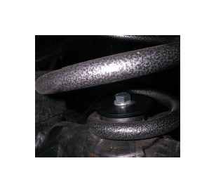
14. Feed the top of the coil into place over the spring guide and lift the bottom of the coil up onto the axle spring guide post.
15. With the springs in place raise the rear axle a bit to take any load off the brake hoses and ABS wiring.
16. Install the rear shocks at the frame end, then raise the rear axle far enough to install the lower end of the shock to the axle bracket, then let the axle hang on the shocks.
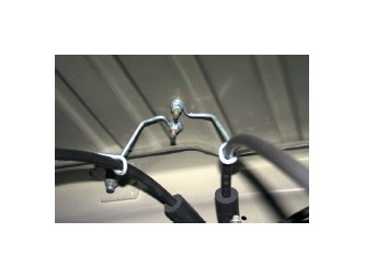
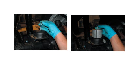
17. Remove the factory rear bump stop from the frame cup and install the bump stop extension, then reinsert the factory bump stop. Use a little grease on both pieces to help them pop into place.
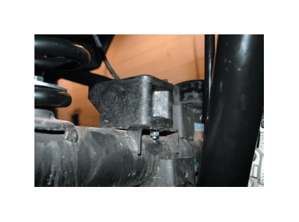
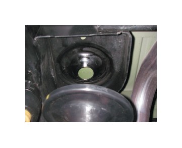
18. Install the lower bump stop onto the axle pad with the 5/16 x 1.25 bolts, washers and nuts provided in the hardware kit. Note: Make sure the bumpstop location is the same as photographed with the extra lip facing the front of the vehicle.
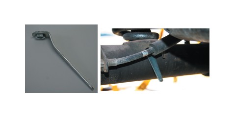
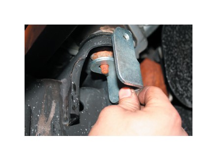
19. To install the rear coil spring retainers on the bottom end of the coil springs first insert the flanged nut into the provided wrench tool, as shown below, and put the nut under the spring pad.
Insert the bolt, with the lockwasher on top of the flat plate, into the rear lower spring retainer, holding the flanged nut in place using the provided wrench tool and begin tightening the bolt. Remove the tool when finished.
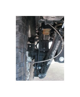
20. Install the new longer rear sway bar links on the inside of the sway bar and axle brackets with special care that the bolts go from the inside out to avoid rubbing on the frame.
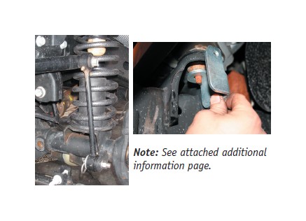
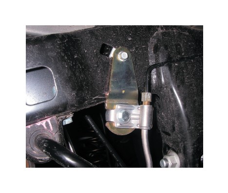
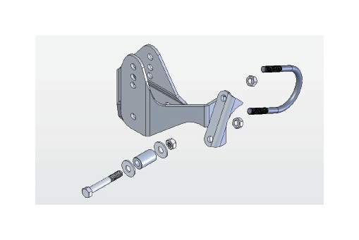
21. Install the rear trackbar bracket at the frame.
Note: See additional instructions for the rear trackbar bracket on the last page.
22. Raise the rear axle far enough to connect the track bar to the new bracket, using the factory bolt and nut.
23. Reinstall the axle breather hose if it was removed during disassembly.
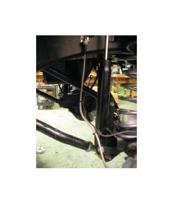
24. Anchor the new rear brake hoses with the angle brackets and clips provided in the hardware kit.
25. Rear installation is now complete.
26. Remove the front skid plate that goes under the transmission. Leave the transfer case crossmember in place.
27. Support the front axle and remove the front shocks.
28. Remove the front track bar.
29. Loosen the front control arm mounting bolts but do not remove them or the control arms yet.
30. Carefully remove the clips that hold the ABS wires in place as needed so they are not damaged as you lower the axle assembly. It may be necessary to disconnect the ABS wires at the connector behind the spring tower to get enough slack to lower the front axle. Use extreme care to not damage the ABS wiring as this is an integral part of the vehicle control system.
31. Carefully lower the front axle and remove the stock coil springs.
32. Replace the front brake hoses with the new longer hoses provided in the kit.
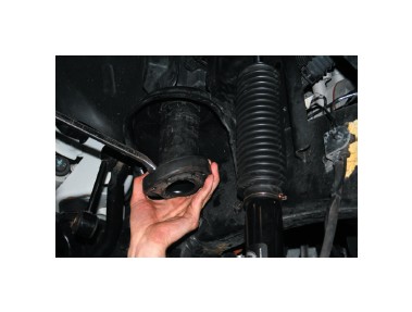
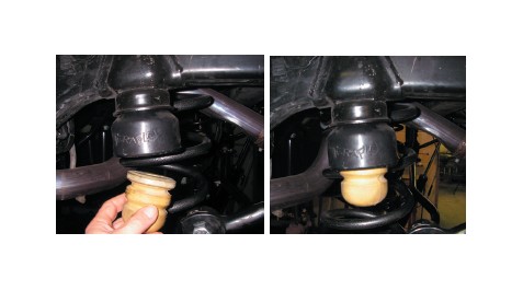
33. Remove the factory upper bump stop from the cup on the bottom of the coil tower.
34. Remove the front upper spring isolator.
35. Install the new front spring spacer.
36. Reinstall the factory spring isolator below the new TeraFlex spring spacer.
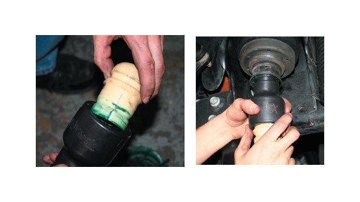
37. Install the new upper bump stop extension by putting some grease on the upper part of the spacer and popping it into the bump stop cup.
38. Insert the factory bump stop into the bottom of the new bump stop extension.
39. Set the length of the front upper FlexArms to 19-1/2”. Final length adjustment will happen during the alignment.
40. Set the length of the front lower FlexArms to 23-3/4”. Final length adjustment will be made during the alignment.
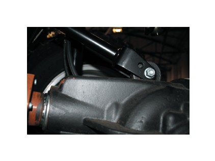
41. Work on one side at a time and replace the lower, then the upper factory control arms with the new FlexArms included in the kit. Repeat on the the other side.
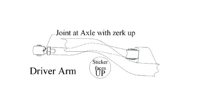
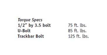
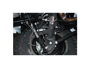
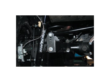
Note: Install the front upper arms as shown in the photo. To avoid removing the exhaust, cut the right front upper control arm bolt on the frame end. A new bolt and nut are included in the kit. Install the new bolt from the outside in. Each lower front FlexArm has a sticker to show where and how to install the arm. Make sure the sticker is up when the arm is installed.
42. Install the front lower bump stops by locating the center of the spring pad on the axle and drilling a 5/16 hole, then use a self tap bolt or a hand tap to create 3/8 coarse threads in the pad. Install the lower bump stops on each side with the 3/8 self tap bolts in the hardward kit.
43. Install the new front springs. Using a coil spring compressor can make this easier.
44. Install the new front shocks.
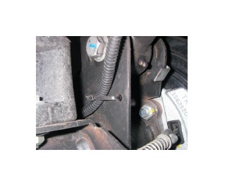
45 . Install the front sway bar quick disconnect links
Note: See attached additional information page.
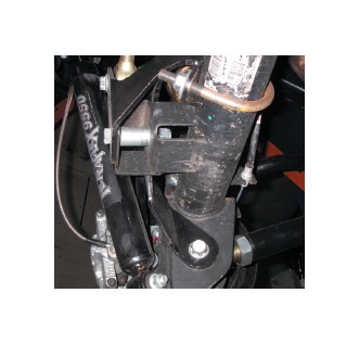
Note: On JK models with the factory disconnect front sway bar it is not necessary to install the QD brackets and pins on the front body mounts. All other models install the brackets and pins where the sway bar links will be parked when disconnected, as shown in the photo.
46. Bleed the brakes being careful to keep fluid in the master cylinder at all times.
47. Reinstall the factory tires or new aftermarket tires and wheels and torque all the lug nuts.
48. Lower the vehicle to the ground.
49. Set the TeraFlex adjustable front track bar length to 33” and install it. Final length may change during the alignment.
50. With the vehicle sitting on the ground re-torque all the control arm mounting bolts and the track bar mounting bolts.
51. Secure the brake hoses and ABS wiring so they will not be damaged during vehicle operation.
52. Have the vehicle alignment checked and adjusted by a shop that is familiar with proper alignment settings on a lifted vehicle.
Note: Caster should be set at 5 degrees. The passenger side may need to be turned 1/4 to 1/2 a degree more to avoid pulling to the right while driving.
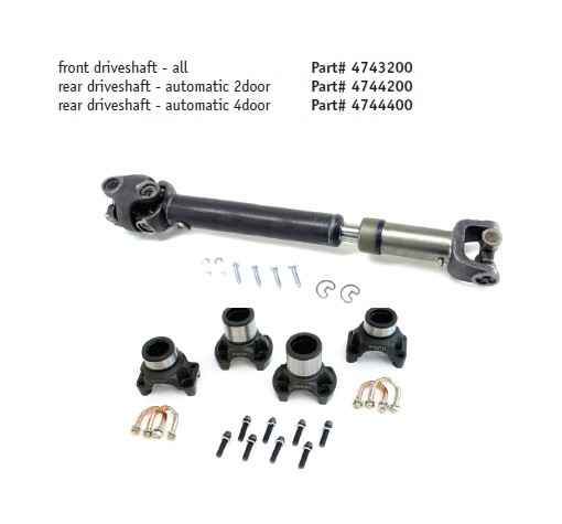
Driveshaft Notes:
The design of the factory driveshafts is great for highway use and mild off road use, but may not survive the rock contacts and stresses of moderate to extreme off-road use once the vehicle is lifted 3 inches or more. TeraFlex driveshafts and yokes are available separately.
Note on tire and wheel selection:
The JK Wrangler uses a larger brake system than on the previous TJ Wrangler so the minimum wheel size is 16 inches. Aftermarket wheels should be selected that are at least 16 inches in diameter with a 5 on 5-inch lug bolt pattern and 4.5 inch backspacing. The factory wheels use a 6 inch backspacing, but when installing larger tires on the factory wheels some rubbing of the tire on the sway bar and control arm links may occur.
TeraFlex offers both wheel offset adapters and wheel lug pattern adapters that are 1.250 inches thick. The offset adapters are for running factory wheels with aftermarket tires. The adapters allow use of a wheel with either a 5 on 4.5 lug pattern or 5 on 5.5 lug pattern on the JK Wrangler bolt pattern of 5 on 5 inches. Contact your local TeraFlex distributor for more information.
Tires from various manufacturers vary in actual dimension, but as a general guideline TeraFlex recommends a maximum tire diamter of 37 inches mounted on a 8-10 inch wide rim for use after installing the JK 4 inch suspension system. Other tire and wheel combinations may also work, but the installer takes responsibility for ensuring a proper selection of tire and wheel.
The 2007 JK Wrangler uses 1/2- inch by 20 (UNF) wheel studs.
Additional Information: JK Wrangler
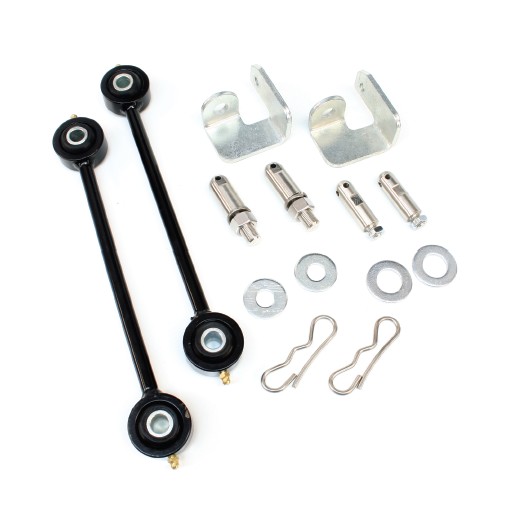
Front Sway Bar Disconnects:
The front sway bar link supplied in your kit may be either a fixed link or an adjustable link. The adjustable link must be set to length and the jam nuts tightened.
Remove the factory sway bar link. Insert the sleeve into the upper bushing. Put the flat washer on the bolt, then the bolt through the sleeve and then through the sway bar. Install the stover nut and tighten.
The lower pin mounts through the factory link mount on the axle, then slide the sway bar link into place, install the large diameter flat washer and the retaining clip.
The angle bracket that is part of the sway bar link hardware can be installed under the body mount to provide a “park” location for the sway bar link when it is disconnected for off-road use. The angle bracket is assembled by putting the threaded end of the smaller pin through the small hole of the bracket and installing the jam nut. Then remove the factory body mount nut and install the bracket on to the body mount stud with the new nyloc nut. This pin is used to “park” the sway bar link when the link is disconnected.
The rear brake line lowering brackets (3-inch kit only. The 4-inch kit includes extended brake and L-Tabs to mount the lines to the frame) are bent in order to allow additional clearance between the brake line and the rear factory sway bar. Be sure to install the left and right brackets so the brake line is moved in away from the sway bar. The locating tab should be located in the slot on the bracket.
NOTE: The rear axle track bar bracket is designed as a bolt on. For extreme off-road use this bracket can be permanently welded to the axle tube and factory brackets.
INSTALLATION:
1. Properly support the rear of the vehicle. Remove the left rear tire.
2. Remove the track bar bolt at the rear axle bracket. You can leave the frame end attached.
3. Remove the left side rear lower control arm bolt at the axle end.
4. Install the new TeraFlex track bar bracket so it sits over the factory track bar bracket and lines up with the lower control arm bolt hole.
5. Reinstall the lower control arm bolt through the new TeraFlex track bar bracket.
6. Use the provided sleeve as a spacer and install the provided 1/2” by 3.5 bolt through the new bracket and into the factory bracket.
7. Install the provided U-bolt and nuts to clamp the bracket to the axle tube.
8. Reinstall the track bar, Torque all fasteners, reinstall the wheel and lower the vehicle to the ground