FREE 1 to 3-Day Delivery on Orders $149+ Details

How to Install Teraflex 241-OR 2Low Kit on your 2007-2013 Wrangler
Tools Required
- 1-1/2" Open End Wrench
- 7/8" Socket or Wrench
- 8mm Socket or Wrench
- 10mm Socket or Wrench
- 13mm Socket or Wrench
- 15mm Socket or Wrench
- 18mm Socket or Wrench
- 32mm Socket
- T40 Torx Bit
- 10mm Hex Bit Socket
- Plastic Mallet
- Impact Wrench
- Torque Wrench
- Pry tool to l

Shop Parts in this Guide
Note: This is for the NV241OR with the 4:1 gear ratio that is found in the Rubicon edition Wrangler. This kit will not work in the standard (2.72:1) NV241 case or NV231 cases that are found in the non Rubicon JK and TJ Wranglers. Please see our website, www.teraflex.biz, to get the correct kit for your application. When the new sector is installed the 4WD light will remain on in 2WD Low. The sector was designed this way so the Jeep computer will not override the off-road functions that are only available in 4WD.
Prior to beginning any work on
your transfer case, please verify
that your kit contains the follow-
ing items.
266900 Sector Assembly [1]
Shift pattern sticker [1]
Reassembly/Installation Notes are included in the disassembly instructions.
Removal of Skid Plate and draining the oil from the transfer case
1. Shift the transfer case into 4Low.
2. Raise and support the vehicle so you can safely work underneath it.
3. With an 18mm socket or wrench, remove the [2] crossmember bolts (#2) that connect the transfer case skid plate (#4) to the crossmember.
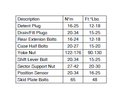
Assembly NOTE: Install the crossmember bolts and tighten them to 65 N•m (48 ft. lbs).
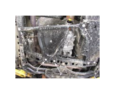
4. With an 18mm socket or wrench, remove the [2] bracket bolts (#3) and remove the transfer case skid plate (#4).
Assembly NOTE: Install these bolts and tighten them to 65 N•m (48 ft. lbs).
5. Position an oil drain pan to catch and store the used oil as it is drained from the transfer case.
6. Use a 10mm Hex socket bit to remove the transfer case drain plug (#3) and drain the oil from the transfer case into the drain pan.
NOTE: Install the drain plug and tighten to 20-34 N•m (15-25 ft. lbs).
Assembly NOTE: Remove the fill plug (#2) with a 10mm hex socket and fill the transfer case with Mopar ATF 4 Automatic Transmission Fluid or equivalent. Correct fill level is to the bottom edge of the fill plug hole. Be sure the vehicle is level to ensure an accurate fluid level check.
NOTE: Install the fill plug (#2) and tighten to 20-34 N•m (15-25 ft. lbs).
Removing the Drivelines
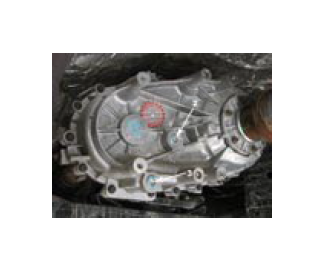
1. Mark a reference line with a paint pen on rear transfer case output yoke. Make a similar mark that lines up with the first mark on the mating rear driveline CV joint. Put another mark on the rear yoke to designate it as the rear yoke so the front and rear yokes do not get interchanged (the front and rear yokes have different diameters for the seals and are not interchangeable). The alignment marks will be used to be sure that it is assembled with the CV joint and the yoke in the same orientation. This is done to avoid driveline vibrations.
2. Using an 8mm socket remove the [8] 8mm bolts (#1) from the rear output flange and disconnect the rear driveline. Support the driveline out of the way to avoid damage to the CV joint that is still attached to the rear differential, or repeat the steps 5 and 6 and remove CV joint from the rear differential.
Assembly NOTE: Compress the driveshaft enough to install it into the transfer case flange.
Assembly NOTE: Align the reference marks on the transfer case yoke (#1) and driveline CV joint (#2).
Assembly NOTE: Install driveline CV joint retainers (#2) and bolts (#1). Tighten bolts to 20 N•m (15 ft. lbs.).
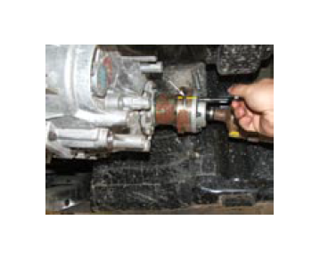
3. Use a 32mm socket and an impact wrench to remove the 22mm flanged nut from the rear output yoke. If you do not have an impact wrench it will be necessary to hold the yoke as you loosen the nut.
Assembly NOTE: Install the rear output yoke onto rear output shaft. Then install and tighten a new yoke nut to 122-176 N•m (90-130 ft. lbs.) torque. The yoke nut is a deformed thread nut and should be replaced whenever it is removed.
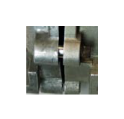
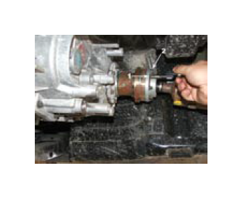
4. Using a puller, remove the rear output yoke. The yoke is a taper fit on the rear output shaft, so a puller is required so it can be removed without damaging.
5. Repeat steps 1-4 for the Front Output yoke and front driveline. Be sure to mark the front yoke to distinguish it from the rear.
Removal of shift cable, detent, and Position Sensor
1. Use the T40 Torx bit to remove the bolt (#2) that holds the Shift Lever (#1) to the sector shaft (#3).
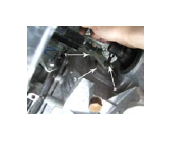
2. Remove the shift lever (#1) from the shift Sector (#3).
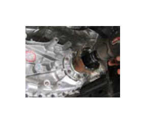
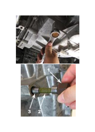
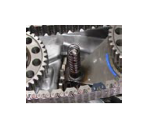
3. Locate the 7/8” hex nut detent plug that is below the sector shaft. Use a 7/8” socket to remove the Detent plug (#1), spring (#2), and plunger (#3).
Reassembly NOTE Install detent plug (#1) in front case. Tighten plug to 16-25 N•m (12-18 ft. lbs.).
4. Unplug the plug for the transfer case position sensor. The sensor is located above the shift lever.Be sure to plug the sensor back in.
Note: the 4WD light is designed to stay on when the vehicle is in 2 Low. This is so the vehicle will not override 4WD functions that are not allowed in 2WD (Lockers, Swaybars, ESC, etc).
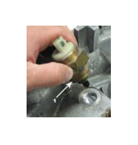
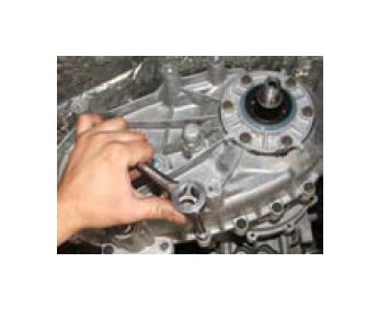
5. Use a 1-1/2” open end wrench to remove the transfer case position sensor.
Assembly NOTE: Tighten the sensor to 20-34 N•m (16-25 ft.lbs.).
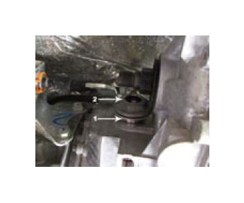
6. Use a 1-1/2” open end wrench to remove the shift support (#2) that holds the seal and the bearing for the shift sector shaft (#1).
Disassembling the Case
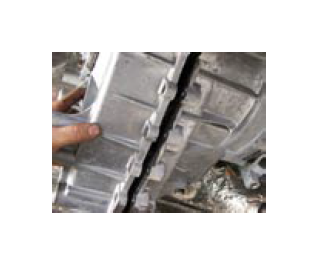
1. Using a 10mm socket, remove the [18] 8mm bolts that hold the 2 case halves together. Some of the bolts may be unique with an extended dog point and require the use of a 13mm socket. Mark the location of the unique bolts with a paint pen for reassembly.
4.Loosen the rear case with a pry tool to break the bead of sealant between the cases
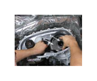
5. Unseat the rear case half from the alignment dowels and remove the rear case and oil pump assembly from the front case assembly.
Caution: Do not loosen the bolts for the oil pump. Chrysler notes that the oil pump should not be removed from the rear case half as the oil pump cover is aligned to the rear output shaft bearing inner race. Loosing the bolts will cause the parts to be misaligned. To insure correct alignment, Chrysler replaces the oil pump assembled to a new rear case half.
6. Remove the spring.
Assembly NOTE: Double check that the magnet is still installed in the pocket in the front Case half.
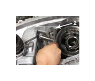
7. Using Lock Ring pliers, remove the front and rear drive sprocket retaining rings.
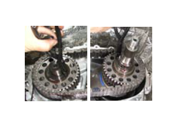
8. Remove the Front and Rear Sprocket and Chain as an assembly.
Assembly NOTE: Be sure to install the three parts as an assembly.
9. Remove the Shift Rail from the shift fork.
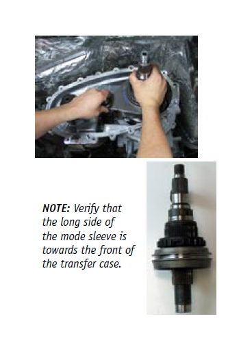
NOTE: The end of the shift rail with the large chamfer points towards the rear of the case.
10. Remove the main shaft, mode fork, and mode sleeve. Take note that the long side of the sleeve is pointed toward the front of the case.
NOTE: Keep them as an assembly.
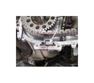
11. Remove the range fork (#1) and hub (#2) as an assembly. Note the fork position so it will be installed the same way.
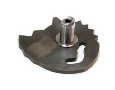
12. Remove the factory shift sector (#2) and discard. This will be replaced with the Tera Low 266900 shift sector.
Assembly
1. Lubricate the Tera Low 2266900 sector with transmission fluid and in the same orientation as the factory sector was (the enclosed slot cam for the range fork is at the front of the case).
2. Repeat the disassembly steps in reverse order. Here are some additional assembly notes:
Assembly NOTE: Shift the transfer case into a 4WD range (the most rearward position is 4low), this will raise the mainshaft slightly and make installation of the rear case half much easier.
Assembly NOTE: Clean mating surfaces of the front and rear housing of any original gasket material.
Assembly NOTE: Verify that the transfer case alignment dowels are properly installed.
NOTE: Apply a thin bead of Silicone Sealer or Gasket Maker to the mating surface of front case. Keep the bead width to maximum of 3/16 inch. Do not use excessive amount of Gasket Maker, as the excess will be forced into case interior.
Assembly NOTE: Align oil pump with mainshaft and align shift rail with bore in rear case. Then install rear case onto the front case. Be sure oil pickup tube is in the correct position during assembly.
CAUTION: Verify that shift rail, and case alignment dowels (3) are seated before installing any bolts. Case could be cracked if shaft rail or dowels are misaligned.
NOTE: Install 4-5 rear case-to front case bolts to hold rear case in position. Tighten bolts snug but not to specified torque at this time. Be sure the unique bolts go back in their original location.
NOTE: Apply Loctite™ 242 to remainder of rear case-to-front case bolt threads and install bolts. Tighten all bolts to 20-27 N•m (15-20 ft. lbs.).
Complete the assembly by reversing the disassembly steps.
3. Install the sticker with the new shift pattern.
4. The 2Low allows for 2WD (rear wheels driving) in low range. This way you can use low range and maintain the ability to easily steer. The 2WD Low position is the first position after Neutral. After the assembly is complete test the shift pattern to be sure you can get into all the available shift positions.
Note to Driver: Shifting may feel different as automatic transmissions do not completely disconnect. You may turn off your engine to make shifting easier, or a slight roll of the tire may help in shifting.