 FREE 1 to 3-Day Delivery on Orders $149+ Details

How to Install a Synergy High Steer Drag Link on your 2007-2014 Wrangler JK

Shop Parts in this Guide
GENERAL NOTES:
- This draglink can be used in the stock configuration or in a flipped high steer layout. These instructions cover both forms of installation. The following notes are in relation to the high steer drag link flip conversion:
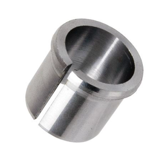
- If doing a high steer conversion, the installation of this draglink will require a tapered reamer of 1.5 in. per ft or the use of a 8001-02-01 TRE adapter sleeve and 13/16” drill bit or an 8001-03-01 TRE adapter sleeve and a 7/8” drill bit. Identify which adapter sleeve is being used before beginning installation.
- This draglink should be used in conjunction with the PPM-8055 front track bar relocation bracket.
- You must use a minimum 3” tall front bump stop extensions to prevent the track bar and draglink from hitting the bottom of the frame at full bump. PPM-8057 (3”) and PPM-8075 (4”) front bump stops are available. 3” tall bumpstop spacers are recommend for using 35” tires and the 4” tall for 37” tires.
1. With a jack stand supporting the passenger side of the front axle, remove the passenger side tire and wheel.
2. Remove the factory draglink from the steering knuckle and pitman arm. A couple of sharp blows with a large hammer to the steering arm and pitman arm will usually pop the taper loose. 3. Note: steps 4-6 are for high steer drag link flip conversion with 8001-02-01. Steps 7-8 are for high steer drag link flip conversion with 8001-03-01. If bolting draglink into stock location, proceed to step 9.
4. If using a tapered reamer (no TRE adapter) and a 1/2” drive hand drill, ream the factory steering knuckle from the top to a diameter of .730”, measured to the large end (top) of the taper. Check fit the new tie rod end and castle nut to make sure the taper is deep enough to install the cotter pin.
5. If using an 8001-02-01 TRE adapter, drill the factory steering knuckle using a 13/16” drill bit and install the flip adapter from the top. Be careful when drilling out the hole to not oblong or enlarge the hole over .880”
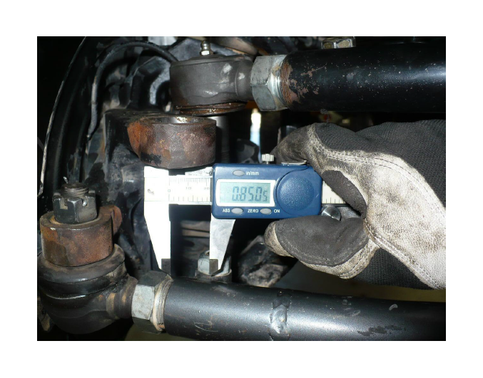
6. The 13/16” (.8125”) drill bit should equate to about a .850” hole due to hand drilling. If additional clearance is needed, use a small dremel tool or die grinder to clearance the hole for the flip adapter to be installed.
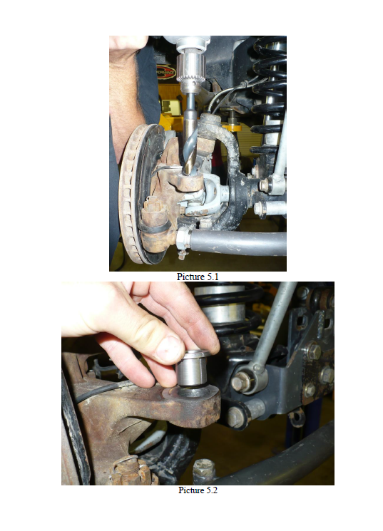
- Any larger than .880” and the flip adapter will not seat correctly in the knuckle. The target finished hole size is between .845” and .875” See Pictures 5.1 and 5.2 for reference.
- Once the hole is drilled to size, install the flip adapter. DO NOT hammer the flip adapter into knuckle. Gently pinching close the gap before tapping in will help get the adapter started. See images below.
7. If using an 8001-03-01 TRE flip adapter, drill the factory steering knuckle using a 7/8” drill bit and install the flip adapter from the top. Be careful when drilling out the hole to not oblong or enlarge the hole over 1.00”
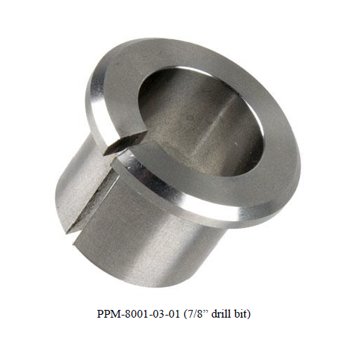
8. The 7/8” (.875”) drill bit should equate to about a .900” hole due to hand drilling. If additional clearance is needed, use a small dremel tool or die grinder to clearance the hole for the flip adapter to be installed.
9. The draglink comes assembled with the tie rod ends fully threaded in, do not make any adjustments prior to installing on the vehicle.
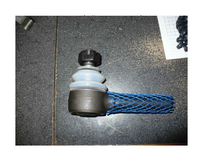
10. Attach the draglink to the steering arm and pitman arm using the supplied boot and castle nut. Dust boots will ship with the lower spring pictured as shown below.
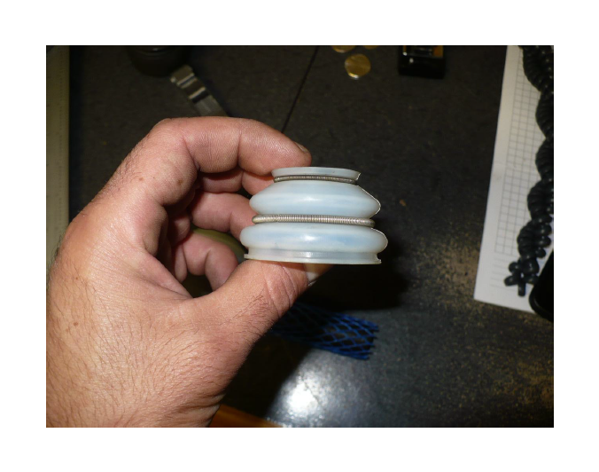
11. Install dust boot onto tie rod end and roll lower spring down to the bottom lip of the dust boot as pictured below.
12. Tighten the castle nut to 55 ft-lbs or more to align the cotter pin hole. Install the cotter pin on the steering arm end and bend the ends over. Do not install the cotter pin at the pitman arm side at this time.
13. Align the draglink so the bend is flat and towards the front. Snug the jam nut on the pitman arm tie rod end, do not fully tighten at this time.
14. Adjust the draglink to center the steering wheel by using the adjuster sleeve on the passenger side tie rod end (steering knuckle end). This requires a 1 ¼” wrench. Tighten the pinch bolt to 50 ft-lbs. Check rotation of bar up and down so there is no contact with the tie rod or other components. Adjust draglink as necessary so no contact can be made.
15. Next, take a short test drive. If the steering wheel is not centered the ESP light will come on, so make sure you adjust the draglink so the steering wheel is perfectly centered. This can be achieved by a short test drive and making the necessary adjustments. When driving in a straight line take note of which way the steering wheel needs to turn to be centered. If the steering wheel needs to turn right to be centered, shorten the draglink. If the steering wheel needs to turn left to be centered, lengthen the draglink.
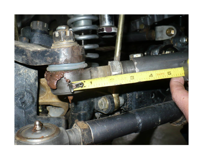
16. Adjust the draglink as needed. NOTE, do not adjust the double adjuster out further than 3.25” from center of tie rod end to the end of the draglink. If additional adjustment is needed, unthread the tie rod end from the pitman arm side. See picture below showing the maximum safe adjustment for reference.
17. At this time, fully tighten the jam nut at the pitman arm side. Really crank this down as jam nuts tend to loosen up if not fully tight. Also, do not forget to install the cotter pin at the pitman arm side. Double check all bolts / torques before driving and recheck bolt torques after 100 mi of driving.
Installation is Complete
