 FREE 1 to 3-Day Delivery on Orders $149+ Details

How to Install Synergy Frame Side Rear Lower Control Arm Gusset Kit (07-18 Wrangler JK) on your Jeep Wrangler
Installation Time
2 hours
Tools Required
- Basic simple hand tools.
- 4-1/2” angle grinder with sanding disc, or 3” air sander with sanding disc to prep surfaces for welding
- Welder. Mig is preferred, but stick or Tig are acceptable as well.

Shop Parts in this Guide
GENERAL NOTES:
These instructions are also available on our website; www.synergymfg.com. Check the website before you begin for any updated instructions and additional photos for your reference.
This is a weld on gusset kit and should be installed by an experienced welder.
We recommend installing one side at a time.
**Note** Gas tank removal will be required if 502202-03 Inner gusset plate is desired to be installed on the passenger side. Steps 9-21 will cover gas tank removal.
PARTS LIST:
PART NUMBER – PART DECRIPTION
(2) 502202-01 Rear Lower Control Arm Outer Gusset Plate
(2) 502202-02 Rear Upper Control Arm Gusset Plate
(2) 502202-03 Rear Lower Control Arm Inner Gusset Plate
INSTALLATION:
1) Installation can be done with the vehicle on the ground and control arms in place, however we advise to remove control arms as to not melt suspension joint bushings during welding.
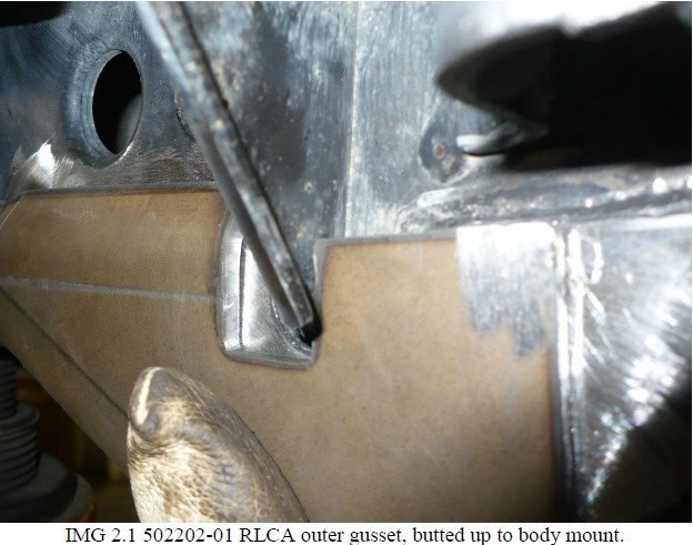
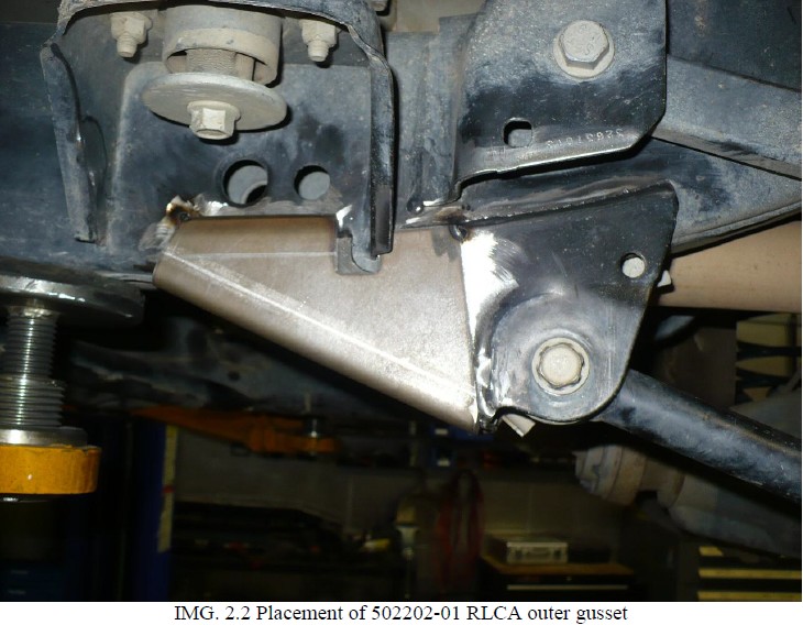
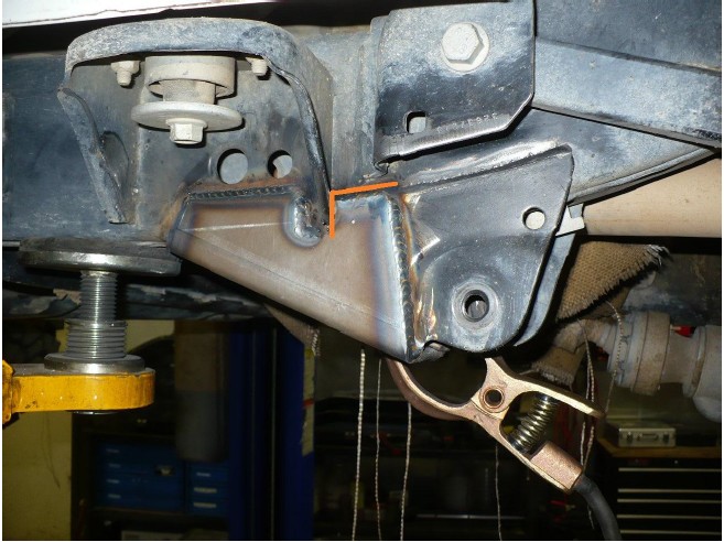
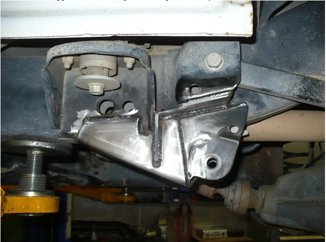
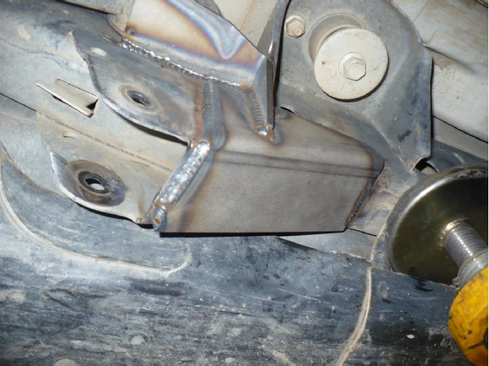
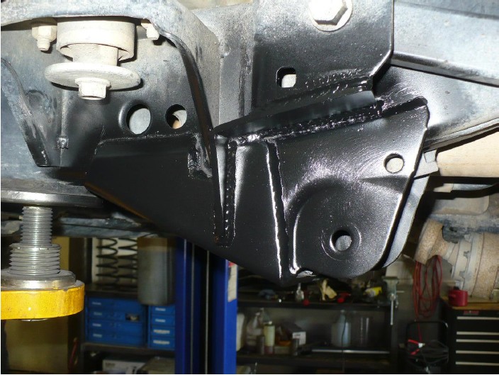
2) Start on the driver’s side. Begin by test fitting gusset plates onto the vehicle and marking which areas need to be prepped for welding. The 502202-01 RLCA Outer Gusset Plate should butt up to the rear body mount as shown in image 2.1 and 2.2 below.
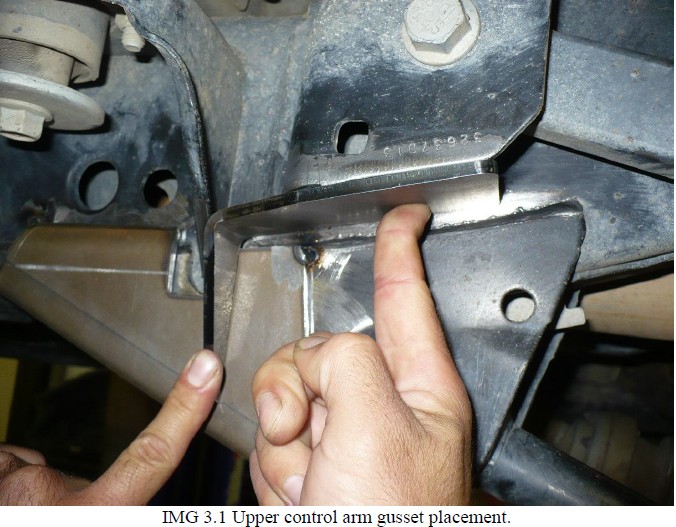
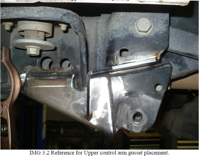
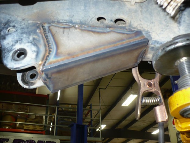
3) Next, test fit 502202-02 Rear Upper Control Arm Gusset. Again, bracket should butt up to rear of body mount as shown in IMG 3.1 and 3.2 below.
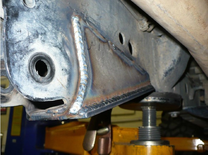
4) Tack 502202-01 outer gusset into place and fully weld the seam highlighted in red in image 4.1 below as it will be difficult to weld once all remaining plates are in place. Do not weld inner side of bracket at this time, only outer seams as shown.
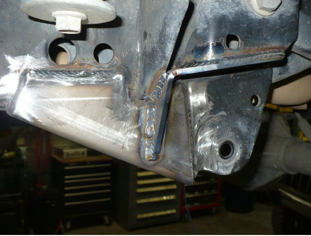
5) Tack 502202-02 rear upper control arm gusset into place. Fully weld once desired fitment is achieved.
6) Lastly, test fit 502202-03 inner gusset in place. Take note of which areas to prepare for welding.
7) Tack inner plate into position. Once satisfied with fitment, fully weld all seams as shown.
8) Driver’s side installation is complete. Passenger side is the same up until step 6 where fitment of inner gusset takes place. To properly fit and install the inner gusset plate, the gas tank must be removed for adequate clearance.
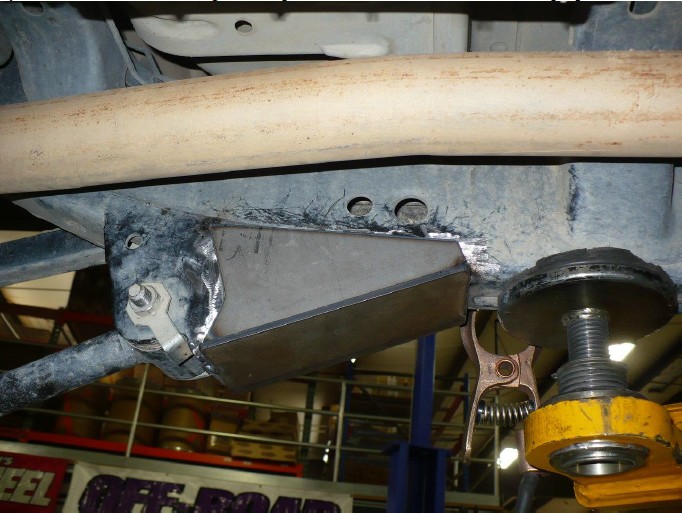
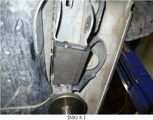
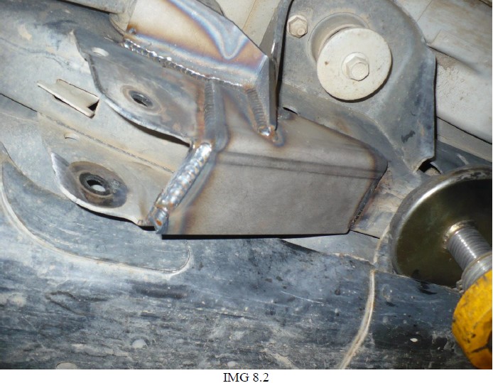
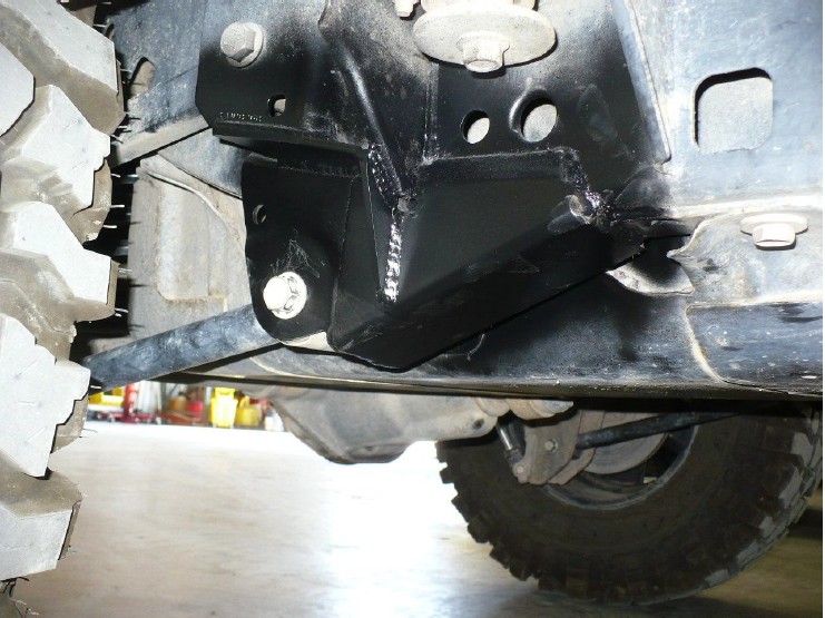
If gas tank removal is not desired, install outer gussets only as shown. Careful when welding around the plastic portions of the gas tank. Completed gussets should appear as shown in IMG 8.1 & 8.2 below.
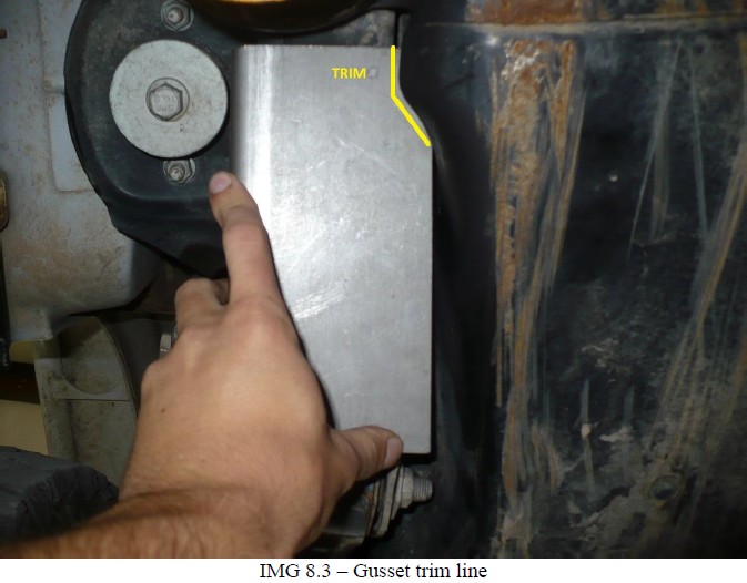
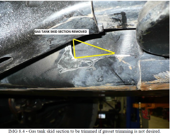
Note, some trimming of factory gas tank skid or LCA skid is required for fitment. See Images 8.3 & 8.4 below.
If gas tank removal is desired, proceed to step 9 for instructions on removal.
9) Drain the gas from the tank if it’s not close to empty. You can do this by removing the filler hose form the fuel tank and inserting a drain hose, it needs to be a small hose because there is a flapper valve installed into the opening.
10) Remove the stock T-case skid plate or any aftermarket T-case skid plate
11) Loosen and remove the passenger side rear lower control arm bolt, pull the bolt out so it is flush with the inside of the lower control arm bracket
12) It is very helpful to remove and install the tank if you remove the right rear coil spring and disconnect the drive shaft at the pinion
WARNING: The fuel system is under constant pressure even with engine off. Before servicing fuel rail, fuel system pressure must be released.
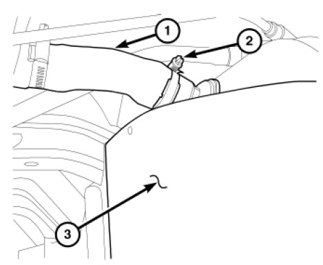
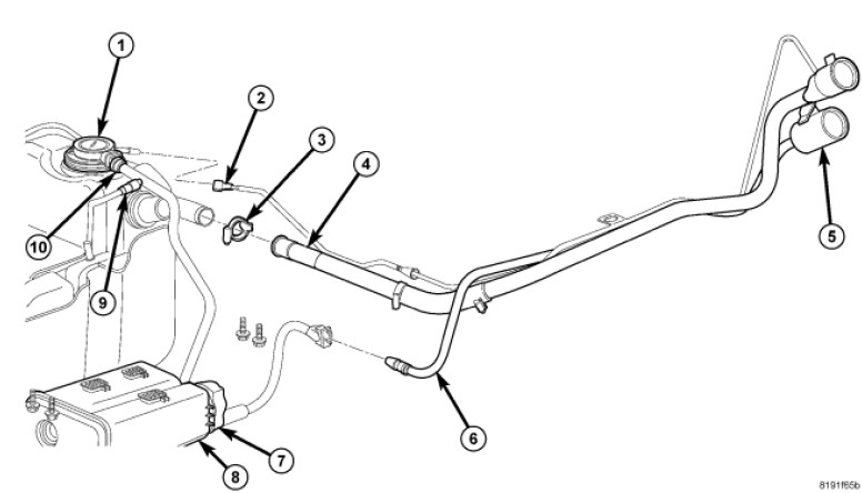
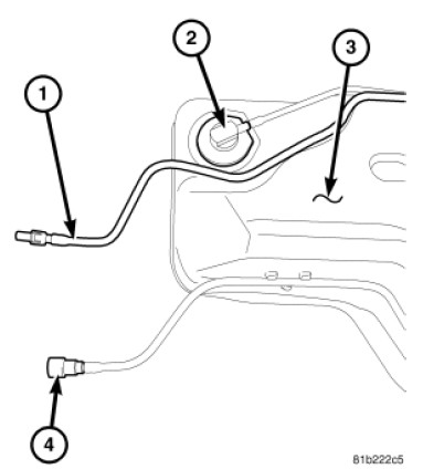
13) Remove fuel fill hose clamp (2) at rear of tank (3).
14) Remove fuel fill hose (1) from fuel tank.
15) Disconnect quick-connect fitting (2), (9) and (10)
The fuel tank skid plate and the fuel tank assembly are removed at the same time. They share common fasteners.
16) Support tank with a hydraulic jack.
17) Disconnect quick-connect fittings at front of tank (1) and (4)
18) Remove all of the tank mounting bolts.
19) Partially lower tank to gain access to pump module electrical connector.
20) Disconnect electrical connector at fuel pump module.
21) Continue lowering tank for removal.
22) Once removed, tack and weld 502202-03 Inner gusset plate in the same fashion as the driver’s side.
23) Deburr all welds and paint exposed areas of metal to prevent rust.
24) Reinstall gas tank in the reverse order of removal (steps 10-21) Tighten the factory gas tank frame bolts to 30 ft-lbs.
25) Reinstall any control arms removed for installation of gusset kit and torque to mfg specifications. (125 ft-lbs for OEM, or 9/16” Gr8 hardware.)
Installation is Complete

