 FREE 1 to 3-Day Delivery on Orders $149+ Details

How to Install Synergy Adjustable Front Lower Control Arms (07-18 Wrangler JK) on your Jeep Wrangler

Shop Parts in this Guide
GENERAL NOTES:
These instructions are also available on our website; www.synergymfg.com. Check the website before you begin for any updated instructions and additional photos for your reference.
The installation of these control arms will allow you to correctly align the front axle after a suspension lift kit is installed.
These control arms feature a double adjuster sleeve which allows you to adjust the length of the arm without removing the arm from the vehicle.
These control arms feature Synergy DDB bushings which are a free floating Teflon lined bushing that requires no grease for the duration of their use.
PARTS LIST:
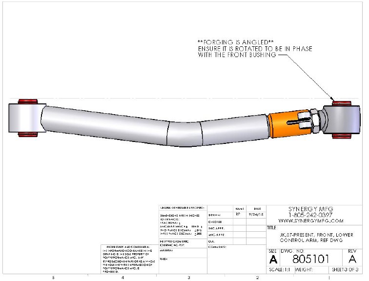
8051- JK, 07-PRESENT, FRONT, LOWER CONTROL ARMS
(1) 805101-L JK, 07-PRESENT, FRONT, LOWER CONTROL ARM, LEFT (ASSEMBLED)
(1) 805101-R JK, 07-PRESENT, FRONT, LOWER CONTROL ARM, RIGHT (ASSEMBLED)
INSTALLATION:
1. The control arms come assembled to the shortest length. Make any length adjustments by only turning the adjuster sleeve so there is equal thread on the flex joint and adjuster sleeve.
2. We recommend that you preset the length of the lower control arms. For 3-4.5” of lift, we recommend a length of 23.25” measured from the center to center of the bushings. This length is a good starting point when using the stock length upper control arms, the final length should be adjusted to get the correct amount of castor, usually 4-6 degrees. If you are also using adjustable upper control arms, set the lower control arms to 23.25”, start the upper control arms at the factory lengths, and then adjust the uppers to get the correct amount of castor angle.
3. Remove the existing lower control arms. If you are just replacing the lower control arms, they can be replaced one at a time with the vehicle sitting on level ground, without removing the tires & wheels or any other suspension part.
4. The 8051 control arms are left and right specific. Be sure they are installed correctly and the forged housing is aligned properly. The forging at the adjuster end of the control arm is angled so that the bushings are put in a zero bind condition at ride height.
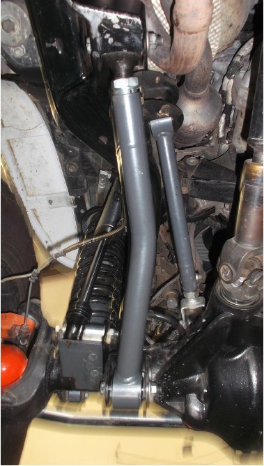
5. Install the new control arms with the adjuster at the frame end. The arms are bent in for tire clearance, and up for ground clearance. Be sure to install them correctly. Reuse the factory mounting bolts.
NOTE: When installing with an aftermarket axle housing, the control arm mounting brackets on the axle may be different than stock. Because these control arms are bent for maximum ground clearance and tire clearance, slight clearancing of the control arm brackets may be required to prevent interference.
6. Tighten the factory control arm bolts to 125 ft-lbs. Once final length adjustments are made, ensure the vehicle is at ride height and tighten the pinch bolt to 80 ft-lbs. Put a wrench on the adjuster sleeve at this time and try to move the adjuster. Make sure pinch bolt has adequately clamped onto the flex joint shank so that the adjuster is not movable. If movable, increase torque on pinch bolt but do not exceed 90 ft-lbs.

7. Re torque bolts after the first 100 miles of driving.
8. Installation is complete.
