


Installation Time
(approx) 4 Hours
Difficulty Level:
Mechanical expertise or professional installation required.
Installation Guides
No guide available for this part yet.
 FREE 1 to 3-Day Delivery on Orders $149+ Details


$214.43 kit
CONFIRM THIS FITS YOUR VEHICLE!
Saved - View your saved items
We're sorry. We couldn't save this product at this time.
or use
Features, Description, Reviews, Q&A, Specs & Installation
| Brand | Supreme Suspensions |
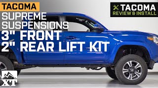
| Lift Height | 3.00 Inch |
| Lift Kit Type | Spacer Lift |
| Lift Kit Max Tire Size | 33 Inch |
| Brand of Shocks | Supreme Suspensions |
| Shock Style | No Shock |
Better Ground Clearance with an OE Feel. Give your Toyota Tacoma better ground clearance, while keeping its OE ride comfort and feel with the Supreme Suspensions 3-Inch Front & 2-Inch Rear Pro Billet Lift Kit. This lift kit adds 3 inches front, and 2 inches rear lift without radically changing your drivetrain and suspension configuration, so your Toyota Tacoma drives the same. Besides better ground clearance, this lift kit levels the front to the rear, improving your truck’s stance.
Precision-Crafted Blocks & Spacers. The Supreme Suspensions 3-Inch Front & 2-Inch Rear Pro Billet Lift Kit manages its lift by using lift blocks and spacers that are CNC-machined from solid billets of 6061-T6 aircraft aluminum. This solid construction results in components that are extremely strong, lightweight, and durable compared to welded or even cast spacers. Also, the rear and front spacers are hard anodized in black for additional protection against corrosion.
Available with Differential Drop & Skid Plate Spacers. Included with the Supreme Suspensions 3-Inch Front & 2-Inch Rear Pro Billet Lift Kit are skid plate, and differential drop spacers. These spacers are also CNC-machined from 6061-T6 aircraft aluminum, offering just as much strength as the lift spacers. The differential spacers work to lower your Tacoma’s front differential to avoid wear on the CV joints. The skid plate spacers, on the other hand, keep the skid plate from rubbing against your newly modified suspension components.
Trouble-Free Bolt-On, Installation Without Modifications. The Supreme Suspensions 3-Inch Front & 2-Inch Rear Pro Billet Lift Kit bolts-on directly using factory locations, without the need for modifications. This kit includes all mounting hardware for a trouble-free install procedure. Please note that a wheel alignment is recommended after installation.
A Limited Lifetime Warranty Backing. The Supreme Suspensions 3-Inch Front & 2-Inch Rear Pro Billet Lift Kit is backed by a limited lifetime warranty covering material and workmanship defects. Please visit the manufacturer’s website for more details.
Application. The Supreme Suspensions 3-Inch Front & 2-Inch Rear Pro Billet Lift Kit fits all 2005 to 2023 Toyota Tacoma 4WD 6-Lug models.
Supreme Suspensions TYTA05FK3020A
CA Residents:  WARNING: Cancer and Reproductive Harm - www.P65Warnings.ca.gov
Installation Info
Installation Time
(approx) 4 Hours
Difficulty Level:
Mechanical expertise or professional installation required.
Installation Guides
No guide available for this part yet.
What's in the Box
Tech Guides: