 FREE 1 to 3-Day Delivery on Orders $149+ Details

How to Install SuperLift 4 in. Suspension Lift Kit w/ Superide Shocks (03-06 Wrangler TJ) on your Jeep Wrangler

Shop Parts in this Guide
INTRODUCTION
Installation requires a professional mechanic. Prior to beginning, inspect the vehicles steering, driveline, and brake systems, paying close attention to the track bar, suspension link arms and bushings, anti-sway bars and bushings, tie rod ends, pitman arm, ball joints and wheel bearings. Also check the steering sector-to-frame and all suspension-to-frame attaching points for stress cracks. The overall vehicle must be in excellent working condition; repair or replace all worn parts.
Read instructions several times before starting. Be sure you have all needed parts and know where they install. Read each step completely as you go.
NOTES: If the optional Rockrunner System is being installed, refer to those instructions before proceeding.
• An inclinometer, or similar angle measuring tool, is required for a rear driveshaft angle reading. If this tool is unavailable, proper shaft angle can be attained by trial and error.
• Front-end realignment is necessary.
• A factory service manual should be on hand for reference. The manual will contain fastener torque specs, assembly techniques, and special tool requirements that are unique to this particular year and model vehicle.
• Do not add or fabricate any components to gain additional suspension height.
• Any welding must be performed by a professional certified welder.
• After drilling, file smooth any burrs and sharp edges or stress cracks may develop.
• Paint or undercoat all exposed metal surfaces.
• Prior to attaching components, be sure mating surfaces are free of grease, grit, oil, undercoating, etc.
• A torque specification in foot pounds is shown in parenthesis “( )” after each fastener.
• Use the check-off box “” found at each step to help keep your place. Two “” denotes that one check-off box is for the driver side and one is for the passenger side.
• An arrow on diagrams indicates which direction is towards “front of vehicle”.
• Retain all factory hardware for reuse, unless otherwise specified.
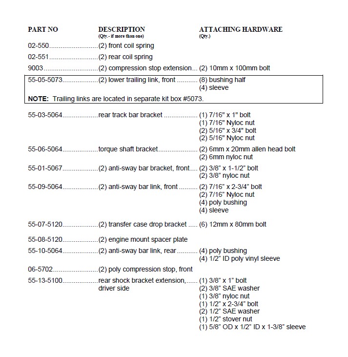
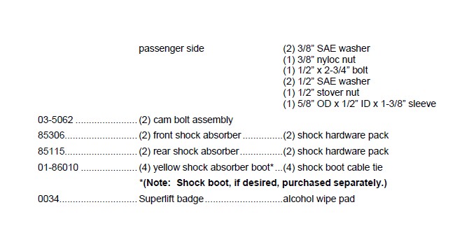
The part number is stamped into each part or printed on an adhesive label. Identify each part and place the appropriate mounting hardware with it.
FRONT DISASSEMBLY
1) PREPARE VEHICLE...
Place vehicle in low gear or park. With the suspension supporting vehicle weight, and the vehicle on level ground, use an inclinometer to take a rear driveshaft angle reading. One of the last installation steps will be to reset the driveshaft angle as close as possible to this reading.
Place vehicle in neutral. Raise front of vehicle with a jack, and secure a jack stand behind the lower link arms, beneath each frame rail. Ease the frame down onto the stands. Support the outboard end of the driver and passenger side axle tube with a floor jack; the frame is to remain on the stands.
2) TRACK BAR...
Remove the bolt at the bottom / axle end of the track bar. The upper / frame end is not disconnected.
3) DRAG LINK and PITMAN ARM...
Remove the cotter pin and nut that connects the drag link-to pitman arm. Use a puller tool to detach the link from the arm.
4) SHOCK ABSORBERS...
Disconnect and discard the factory shocks.
5) ANTI-SWAY BAR LINKS...
On each side, disconnect the sway bar link from the axle bracket and the bar body.
6) SKID PLATE…
Remove and discard the factory front skid plate that is forward of the “belly pan” for the transmission.
7) LOWER LINK ARMS...
Cam bolts attach the lower links to the front axle housing. Front end alignment is altered as the bolts are rotated. Paint or scribe alignment marks on each cam bolt and axle bracket so the bolts can later be returned to their original position.
On each side, remove the cam bolt assembly from the link’s axle end. Then remove the attaching bolt at the rear of the lower link arm where it connects to the frame rail and remove the link. Save all hardware for reuse.
8) COIL SPRINGS...
Lower the jack/axle assembly until the coil springs are free from their upper seats. A retainer clip must be removed at the base of the driver side coil. Remove the coils.
FRONT ASSEMBLY
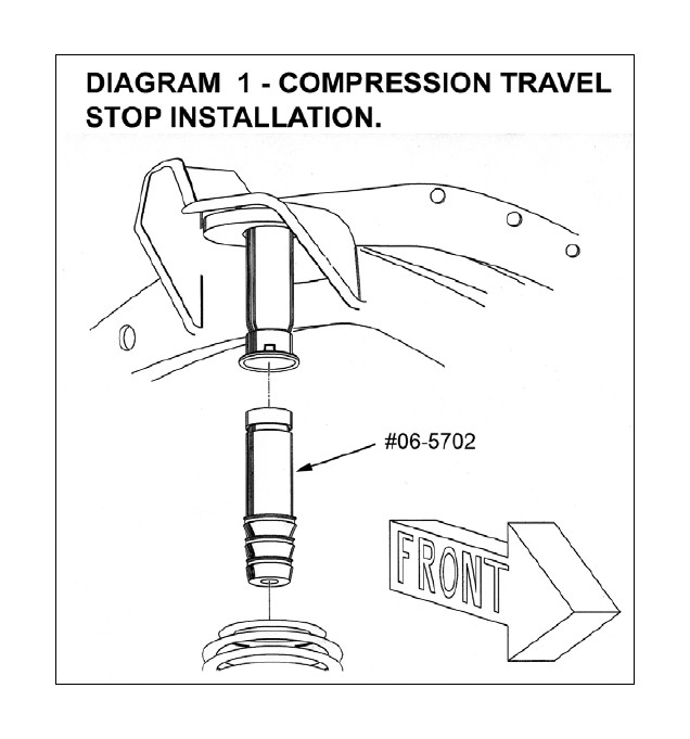
9) COMPRESSION TRAVEL STOPS: (qty. 2) #06-5702...
[DIAGRAM 1] On each side, pry the factory compression stop from its mounting cup, taking care not to damage the cup.
Install the replacement poly compression travel stops (#06-5702) in the factory cups. It may be necessary to raise the axle in order to press the stops in the cups. It may also be necessary to trim the end of the stop slightly so that the stop’s retaining groove fully engages the tabs in the cup.
10) COIL SPRINGS #550...
Lower the axle far enough to facilitate installing the coil springs. Use caution to prevent over-extending brake lines, vent hoses, etc.
Install the coils. Position the coil in the tower first, then slide it into place on the axle seat.
Reattach the retaining clip at the bottom of the driver side coil. 11) LOWER LINKS...
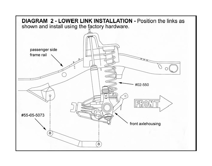
Lubricate and install the supplied bushings and sleeves in the 55-05-5073 lower links.
[DIAGRAM 2] On each side, install the 5073 lower links using the factory hardware. The cam bolts install at the axle with the nut side facing inboard. Only hand tighten the cam bolts; they, along with the links’ rear eye bolts, are fully tightened in a later step.
12) SUPERLIFT SHOCK ABSORBERS...
On each side:
Install shock boot and decal.
With the lower half of the stem hardware in place, insert the top end of the shock through the hole in the factory shock tower. Install the other half of the hardware and tighten only until the bushings start to swell slightly. Install jam nut.
Attach the lower end of the shock to the axle using the factory hardware (21).
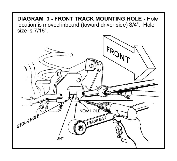
13) TRACK BAR...
NOTE: If the optional Superlift adjustable track bar (#5070) has been purchased, install now per separate instructions.
[DIAGRAM 3] Drill a new 7/16” diameter mounting hole in the track bar’s axle bracket, where shown.
Shift the axle assembly as necessary to align the track bar eye with the new hole. Insert the stock fastener and hand tighten only; the bolt will be fully tightened in a later step.
14) DRAG LINK
Connect the drag link to the pitman, tighten nut (60), and install new cotter pin. If the castellations and the cotter pin do not align, tighten (do not loosen) the nut until they align.
15) ANTI-SWAY BAR LINKS: (qty. 2) #55-09-5064 FOR FRONT ANTI-SWAY BAR LINK...
Note: If optional Superlift Quick Disconnect links are being used, install now per separate instructions.
Attach a #55-01-5067 bracket to each end of the sway bar body using a 3/8” x 1-1/2” bolt and nyloc nut (23). Insert the bolt facing up, and be sure the bracket legs are facing downward.
Install the supplied bushings and sleeves into the eyes of each #55-09-5064 anti-sway bar link. Note that the smaller ID sleeve installs on the upper end of each link.
Position the upper end of each link into the #55-01-5067 bracket and secure using the supplied 7/16” x 2-3/4” bolt (38). Note that the bolts should be installed from the outside.
Slide the lower end of each link into the stock brackets on the axle and secure using the stock hardware. Tighten to factory specifications.
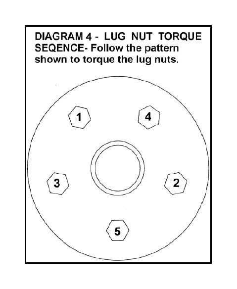
16) TIRES / WHEELS...
CAUTION: Before installing each wheel, be sure to remove any built-up corrosion on the wheel mounting surfaces. Ensure wheels are installed with good metal-to-metal contact. Improper installation could cause loosening of the wheel nuts. Never use oil or grease on lug studs or nuts.
[DIAGRAM 4] All wheel nuts should be tightened just snug, then gradually tightened in sequence to the proper torque specification (80 to 110).
With front of vehicle still on stands, and suspension “hanging” at full extension travel, turn steering lock-to-lock while checking components for proper operation and clearances. Remove jack stands and lower vehicle to floor.
17) TIGHTEN the SUSPENSION COMPONENTS... The suspension must be supporting the vehicle’s weight when these components are torqued:
Lower link arm-to-axle cam bolt nut (85). Before tightening, match-up the alignment marks on the cams and axle brackets that were made in Step 6.
Lower link arm-to-frame nut (130). Track bar-to-axle bolt (55).
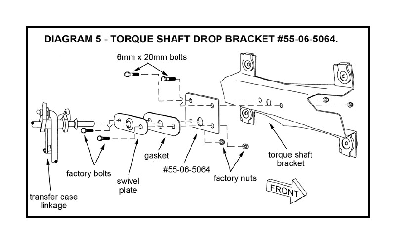
18) TORQUE SHAFT BRACKET #55-05-5064... The torque shaft bracket is part of the transfer case shifter assembly. This step prevents shifter bind after the case is lowered.
[DIAGRAM 5] From under the vehicle, locate the torque shaft bracket. It is attached to the inside of the transmission tunnel and acts as a pivot for the transfer case shift lever. Remove the two bolts that attach the swivel plate-to-bracket. Also remove the swivel plate gasket.
Attach the swivel plate and gasket to the Superlift torque shaft bracket (#55-06-5064) using the factory bolts and nuts (18).
Insert the torque shaft through the swivel plate, then attach the “06” bracket to the factory torque shaft bracket as shown using the supplied 6mm x 20mm allen head bolts and nuts (18).
19) ENGINE MOUNT SPACERS…
Loosen, but do not remove, the transmission mount.
Place a block of wood under the transmission bellhousing and engine oil pan and position a jack so that it supports, but does not raise, the engine. Take precautions to avoid damaging any components.
On each side, remove the two bolts that secure the engine mount to the frame. Save all hardware for reuse.
Carefully raise the engine approximately 3/8” and slide the engine mount spacers (#55-08-5120) between the engine mount and frame mount.
WARNING: Use extreme caution to avoid placing fingers or any other body parts between the engine and frame at any time while the engine is unbolted from the frame.
Line up the bolt holes in the engine mounts, spacer plates, and frame, then lower the engine. Reinstall the factory hardware and tighten to factory specifications.
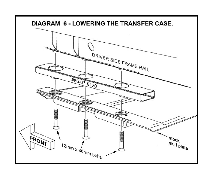
20) LOWERING the TRANSFER CASE: #55-07-5120...
[DIAGRAM 6] Position a jack beneath the driver side of the transfer case crossmember / skid plate, just inboard of the plate-to-frame mounting bolts. Load the jack so that it will support the plate’s weight when the three bolts are removed. After removing the driver’s side bolts, loosen (do not remove) the passenger’s side plate-to-frame bolts.
Lower the jack just enough to install the driver side drop bracket (#55-07-5120), and insert the new 12mm x 80mm bolts. Leave bolts loose so the other side can be installed.
Relocate the jack to the passenger side and repeat the installation procedure for the other “07” drop bracket.
Tighten all six plate bolts (31).
Tighten the transmission mount to factory specifications.
REAR DISASSEMBLY
21) SECURE VEHICLE...
Raise rear of vehicle with a jack positioned at outboard ends and secure a jack stand beneath each frame rail, in front of the lower link arms. Ease the frame down onto the stands, but leave a slight load on the jack. Chock front tires. Remove rear tires.
22) SHOCK ABSORBERS...
Disconnect and discard the factory shocks.
23) ANTI-SWAY BAR LINKS...
On each side, disconnect the sway bar link from the axle bracket and the sway bar body.
24) TRACK BAR...
Before removing the bar, mark the driver and passenger end to aid in reassembly. The plastic shield that covers the driver / axle end of the bar is not reused.
25) UPPER LINK ARMS...
On each side, detach the rear end of the arm from the axle. Loosen, do not remove, the bolt at the frame end of the link. This will allow the link to swing out of the way.
26) COIL SPRINGS...
Lower the axle assembly until the coil springs are free from their seats, then remove the coils. Inspect the thin, disc shaped rubber gasket that insulates the top of the coil and replace if necessary.
REAR ASSEMBLY
27) CAM BOLT SLOTS...
On each side, look at the axle bracket that captures the upper link’s rear eye. Knockout the perforated plug that makes the round hole a slotted hole. If necessary, dress the slot with a file and paint the exposed metal.
28) UPPER LINK ARMS...
On each side, use Superlift cam bolt assembly #1-03-5062 to reattach the link to the axle. Install the bolts from the inside so they point outward. Rotate the cams so that the tall side of the lobes point straight up (12 O’clock position). Do not fully tighten; the bolts are torqued in a later step.
On each side, attach the link’s front eye to the frame. Do not fully tighten; the bolts are torqued in a later step.
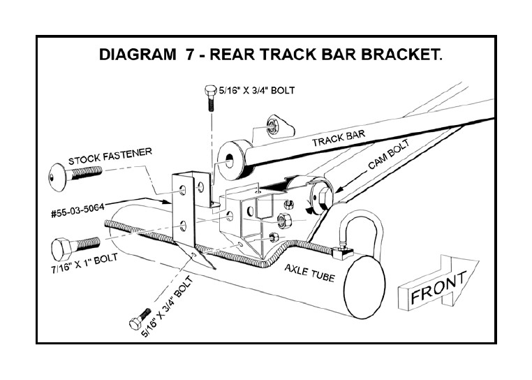
29) TRACK BAR BRACKET #55-03-5064...
[DIAGRAM 7] There are two existing holes in the factory track bar-to-axle mount where the plastic cover was attached. Drill out these holes to 5/16” diameter.
The “03” bracket fits down over the top of the factory mount, as shown. Use the furnished 7/16” fastener at the factory mount’s bar eye hole (37). Tighten the 5/16” hardware (13). The track bar is installed in a later step.
NOTE: It may be necessary to grind down the weld on the factory bracket to ensure the “03” bracket fits flush over the OE bracket. Refer to Diagram 9.
30) COMPRESSION TRAVEL STOP EXTENSIONS: (qty. 2) #9003...
On each side:
Pry the factory compression stop from it’s mounting cup, taking care not to damage the cup. Remove the 10mm bolt that attaches the cup to the spring tower.
Position the Superlift compression stop spacer between the tower and mounting cup, as shown, and install the new 10mm x 100mm bolt (30). Reinstall the factory rubber compression stop into the mounting cup.
31) SUPERLIFT COIL SPRINGS #551...
On each side, position the coil spring on the axle pad. It may be necessary to loosen the lower links’ front and rear eye bolts so the axle can drop enough for coil installation.
Raise the axle until the springs seat in their upper mounts. Do not forget the stock coil gaskets for the top of the coils.
After both coils are in place, jack up the axle assembly until the springs are seated. Be sure the frame rails remain on the jack stands.
32) TRACK BAR...
Install the track bar. Reuse the factory fasteners at both ends. Hand tighten only; both bolts are fully tightened in a later step. It may be necessary to pry the axle assembly over in order to connect the bar.
33) ANTI-SWAY BAR LINKS: (qty. 2) #55-10-5064 REAR ANTI-SWAY BAR LINK...
Note: If optional Superlift Quick Disconnect Links are being used, install now per separate instructions.
Install the supplied bushings and poly sleeves in the eyes of each #55-10-5064 anti-sway bar link.
Position the ends of each link in the stock brackets on the axle and the frame, then secure using the stock hardware. Tighten to factory specifications.
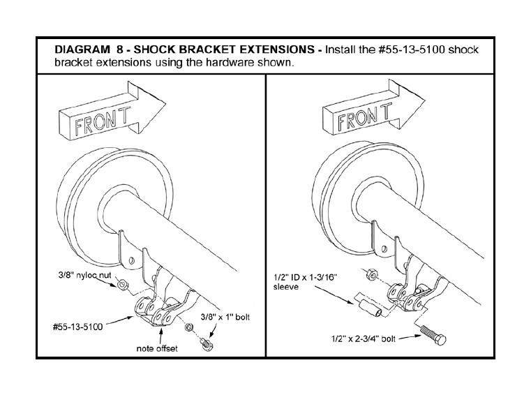
34) SHOCK BRACKET EXTENSIONS AND SHOCKS...
[DIAGRAM 8] On each side, attach the shock bracket extensions (#55- 13-5100 driver side and #55-14-5100 passenger side) to the shock mounts on the axle using the 3/8” x 1” bolt, washer, and nyloc nut as shown.
35) SUPERLIFT SHOCKS...
Install shock boot and decal.
Position shock and tighten the two upper bolts (23) and the single lower bolt (74).
36) TIRES / WHEELS...
CAUTION: Before installing each wheel, be sure to remove any built-up corrosion on the wheel mounting surfaces. Ensure wheels are installed with good metal-to-metal contact. Improper installation could cause loosening of the wheel nuts. Never use oil or grease on lug studs or nuts.
[DIAGRAM 4] All wheel nuts should be tightened just snug, the gradually tightened in sequence to the proper torque specification (80 to 110).
With front of vehicle still on stands, and suspension “hanging” at full extension travel, check all components for proper operation and clearances.
Remove jack stands and lower vehicle to floor.
37) TIGHTEN the SUSPENSION COMPONENTS...
The suspension must be supporting the vehicle’s weight when these components are torqued:
Track bar, both ends (74)
Lower link arm, both ends (130)
Upper link arm, frame end (55)
Upper link arm, axle (cam bolt) end (85)
NOTE: Prior to torquing the cam bolts, again use the inclinometer to take a rear driveshaft angle reading, and compare this to the reading taken in Step 1. Rotate the cam bolts as needed to get shaft angle as close to the Step 1 reading as possible. This will minimize or eliminate shaft vibration due to excessive angle. The 12 O’clock position that the cams were initially adjusted to in Step 28 yields the least amount of angle. It is important that both cams are adjusted identically. To reduce vibration under acceleration, rotate the cams to move the pinion bearing downward. To reduce vibration under deceleration, rotate the cams to move the pinion bearing upward.
38) HEADLIGHTS...
Readjust headlights to factory setting.
39) FINAL OVERALL INSPECTION and TORQUE CHECK...
Perform a front-to-rear inspection. With the suspension supporting vehicle weight, cycle steering lock-to-lock and inspect steering, suspension, driveline, and brake systems for proper operation, tightness, and adequate clearances. Retorque all fasteners.
40) TRANSMISSION SHIFTER MODIFICATION…
This step is only necessary if the vehicle exhibits problems shifting after the lift installation is complete.
Test drive the vehicle and shift through all gears. If it is difficult to shift into (or the transmission jumps out of) Second, Fourth, or Reverse, the shifter is likely hitting the edge of the transmission tunnel due to the transfer case drop and will need to be modified slightly.
Set the parking brake on the vehicle and put the transmission in neutral. Remove the shift knob and upper shifter boot. Shift the transfer case lever into neutral and remove the console, lower shift boot, and dust boot.
Remove the shifter from the transmission following the procedure found in the factory service manual.
[DIAGRAM 9] Disassemble the shifter according to the diagram. Place the lower portion of the shifter in a vice or press and bend it slightly (about 3 degrees) at the point shown. It will be necessary to heat the shifter with a torch in order to bend it in most cases. Do not heat the shifter excessively, and do not bend it more than necessary.
Reassemble the shifter and install it by reversing the steps followed for dissassembly.
41) SAFETY DECAL...
Install “Warning to Driver” decal. Refer to the “NOTICE TO DEALER AND VEHICLE OWNER” section below.
42) ALIGNMENT...
Realign vehicle to factory specifications.

