FREE 1 to 3-Day Delivery on Orders $149+ Details

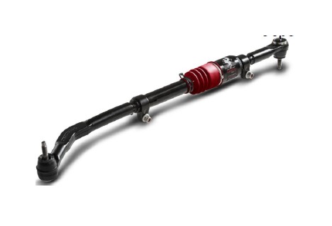
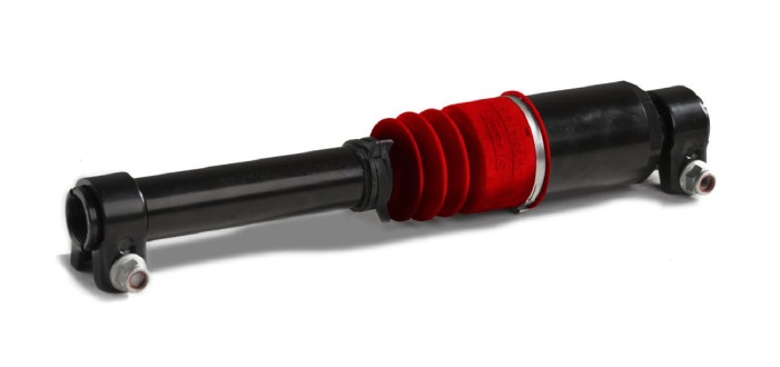
How to Install Steer Smarts YETI XD Bottom Mount Draglink w/ Griffin XD Attenuator - Black Bellow (07-17 Wrangler JK) on your Jeep Wrangler

Shop Parts in this Guide
- Steer Smarts YETI XD Drag Link with Griffin XD Attenuator; Bottom Mount; Black Bellow (07-18 Jeep Wrangler JK)
- Steer Smarts YETI XD Drag Link with Griffin XD Attenuator; Bottom Mount; Red Bellow (07-18 Jeep Wrangler JK)
- Steer Smarts YETI XD Drag Link with Griffin XD Attenuator; No-Drill Top Mount; Black Bellow (07-18 Jeep Wrangler JK)
- Steer Smarts YETI XD Drag Link with Griffin XD Attenuator; No-Drill Top Mount; Red Bellow (07-18 Jeep Wrangler JK)
- Steer Smarts YETI XD Drag Link with Griffin XD Attenuator for High-Steer or Drilled-Out OE Knuckle; Top Mount; Black Bellow (07-18 Jeep Wrangler JK)
- Steer Smarts YETI XD Drag Link with Griffin XD Attenuator for High-Steer or Drilled-Out OE Knuckle; Top Mount; Red Bellow (07-18 Jeep Wrangler JK)
- Steer Smarts Griffin XD Steering Attenuator Upgrade for YETI XD Drag Links; Black Bellow (07-18 Jeep Wrangler JK)
- Steer Smarts Griffin XD Steering Attenuator Upgrade for YETI XD Drag Links; Red Bellow (07-18 Jeep Wrangler JK)
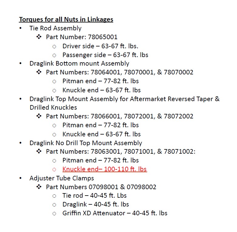
Requirements for Linkage Fit and Func/on
1. Ye# JK Extreme ball studs are designed to be aPached to steering knuckles with stock sized taper holes. If using an aRermarket knuckle, make sure the taper hole has the same dimensions as the stock taper hole. APaching the linkage to an oversized or undersize knuckle taper hole may cause ball stud failure, or premature socket wear out, or failure taper lock.
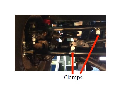
2. Given the numerous aRermarket configura#ons, the draglink and #e rod clamp orienta#ons will need to be checked for interference by turning the wheels from full leR to full right turn. If interference is found, loosen and turn/adjust the clamps as needed to eliminate the interference. The clamps must be located in the clamp posi#oning grooves (sec#ons at each end of the tube with a smaller diameter) before re-#ghtening.
3. Torque all nuts as specified throughout instruc#on and on page 7. EXCESSIVE OVER TORQUE OR UNDER TORQUE COULD CAUSE LINKAGE FAILURE.
4. An aRermarket damper bracket assembly kit for an 1 5/8” diameter #e rod tube is required to replace the original equipment damper bracket.
Special Considerations
1. When installing a complete Ye# JK Extreme linkage; install the draglink before the #e rod for easier access to the draglink knuckle end ball stud nut for #ghtening.
2. For top mount draglink installa#on only, it may be necessary to turn the wheels fully right to gain access to the draglink outer end ball stud nut for #ghtening. If the clearance gained is insufficient, the passenger side #e rod may need to be disconnected.
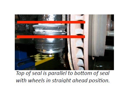
3. While #ghtening the linkage ends into posi#on, make sure the top of the boot seal posi#ons itself around the spacer on the ball stud and does not get pinched between the faces of the spacer and knuckle/pitman arm.
4. A professional wheel alignment is recommended for seOng toe and steering wheel alignment.
How to uninstall the original linkage and install the YETI JK Extreme linkage on your JK Wrangler.

• See page 1 for special considera/ons before beginning linkage installa/on.
• Tie Rod Installa#on: Start at step 1
• Draglink Installa#on: Start at step 7
• No Drill Draglink Top Mount Installa#on: Start on page 5
• Griffin XD APenuator Upgrade: Start on page 6
Tie Rod Installation Instructions
1. Remove the damper from the #e rod steering assembly. (See page 1 for special considera/ons before removing)
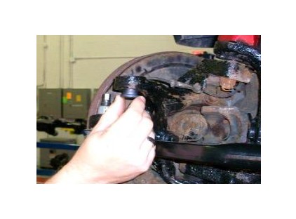
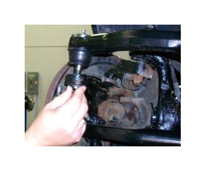
2. Loosen, without removing, the ball stud nuts on the #e rod assembly using a 21mm socket.
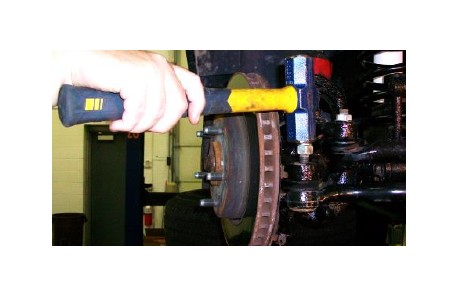
3. Unscrew the nuts un#l the top of the nut is above the end of the ball stud to prevent damage to the ball stud. Using a hammer, break the two stud tapers loose separa#ng the studs from the knuckles.
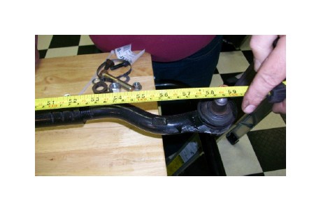
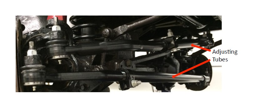
4. Once the #e rod assembly is removed, measure the distance between the ball studs. Set the distance of the YETI XD linkage to match by turning the adjus#ng tube. This will get you close to the correct toe and wheel center distance. Keep driver side and passenger side #e rod threads equal within 2-3 exposed threads.
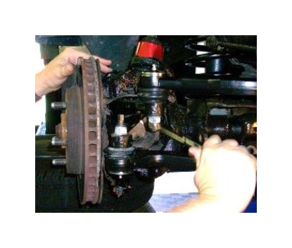
5. Remove plas#c seal shipping protec#ve covers and install your new Ye# JK Extreme #e rod assembly to both knuckles. Proceed to #ghten the ball stud nuts to a torque of 63-67 R.-lbs using a 21mm socket.
6. Make sure that the ar#cula#on on the #e rod ball stud, drivers side, is centered. To achieve this , turn the drivers side #e rod end from one side to the other and then center between the two sides . The seal will look evenly centered when the socket is centered (IMPORTANT). If installing #e rod assembly only, grease all zerks un#l grease purges around boot seal; wipe off excess grease. Torque clamp bolts to 40-45 R. – lbs.
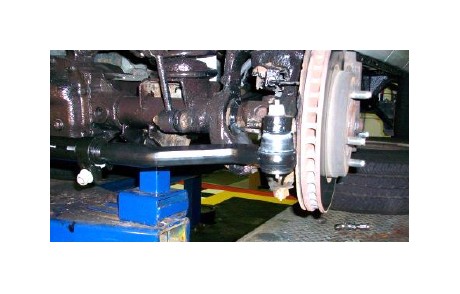
Draglink Bottom Mount Assembly Installation Instructions
7. Repeat steps 2 thru 6 to remove the original draglink assembly and install your new Ye# draglink assembly. Torque the draglink to pitman arm nut to 77-82 R.-lbs and the draglink to knuckle nut to 63-67 R.-lbs using a 21mm socket. Center the ar#cula#on of the draglink at the pitman end of the linkage. To achieve this , turn the pitman side draglink from one side to the other and then center between the two sides. The seal will look evenly centered when the socket is centered. (IMPORTANT)
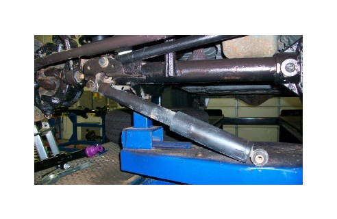
8. ARer seOng toe with the #e rod, and clear vision (straightness of steering wheel while wheels are in the straight ahead posi#on) with the draglink; #ghten the clamps on the assemblies to a torque of 40-45 R.-lbs using 18mm and 15mm sockets. The Tie rod clamp ears should point toward the ground as shown, while the draglink clamp ears should point towards the front of the vehicle to prevent interference between the draglink and #e rod assemblies during opera#on. Grease all #e rod and draglink assembly sockets un#l grease purges around the boot seal; wipe off excess grease. Turn the wheels all the way to the right in order to grease the passenger side draglink socket.
Draglink No-Drill Top Mount Installation Instructions
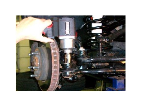
1. If you’re installing a top mount draglink using our patent pending reverse taper mount, twist the selflocking tapered sleeve into the boPom of the knuckle moun#ng hole as shown (The self-locking tapered sleeve is stored between the seal and the plas#c seal shipping protec#ve cover on the drag link outer end.)
2. Install the top mount draglink into the knuckle hole from the top side and #ghten the nut un#l the nylock on the nut engages.
3. Hold the hex, using a 10mm wrench, on the end of the ball stud to keep the stud from turning in the socket while #ghtening the ball stud nut using a 21mm wrench. Tighten un#l approximately 40 R. lbs of torque is achieved. Once the 40 R. lbs of torque is achieved, the nut is to be #ghtened to 100-110 R.-lbs (Very Important) using a 21 mm socket.
4. Make sure toe and clear vision (straightness of steering wheel) are set correctly and all nuts are #ghtened to the specified torque. For the top mount the clamp ears on the #e rod can point up while the clamp ears on the draglink should point towards the ground for greater ground clearance as shown. The last step is to grease both draglink sockets through the zerks un#l grease purges around the boot seal; wipe off excess grease.
Installing the Steer Smarts Griffin XD A[enuator Upgrade in the Ye/ Extreme Draglink
• Loosen the draglink adjus#ng tube clamp nuts.
• Disconnect the draglink from the passenger side knuckle.
• Remove the adjus#ng tube assembly.
• As shown below, thread the Griffin XD APenuator onto the Draglink Pitman End and thread the Draglink Knuckle End into the Griffin XD APenuator un#l approximately three threads are engaged on each side.
• Turn the Griffin XD APenuator while suppor#ng the Draglink Knuckle End to adjust the draglink length un#l the Draglink Knuckle End Ball Stud fits into the knuckle hole.
– The draglink should be as long as it was prior to inser#ng the Griffin XD APenuator with equal thread engagement on both sides within 3 threads.
• Re-assemble the Draglink Knuckle End to the passenger side knuckle. Retorque the ball stud nut to the required torque specified on page 7 depending on which type of draglink is installed.
• Check steering wheel straightness/levelness. If steering wheel is not level turn the Griffin XD APenuator un#l it is.
• Torque the Griffin XD Clamp Nuts to 40-45 R. lbs. as specified on page 7.