FREE 1 to 3-Day Delivery on Orders $149+ Details

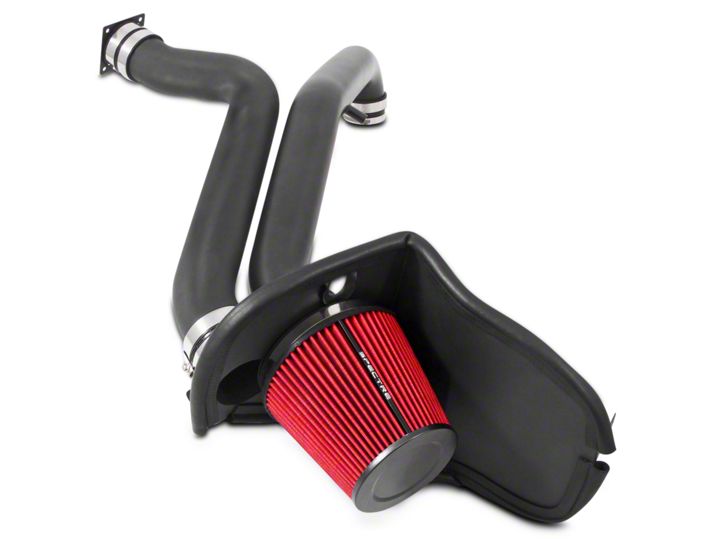
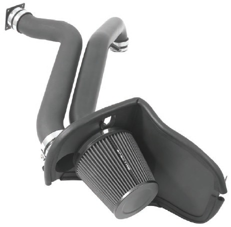
How to Install Spectre Performance Cold Air Intake - Textured Black (97-06 4.0L Wrangler TJ) on your Jeep Wrangler
Tools Required
- 5/16” or 8mm Nut driver
- 10mm wrench
- 10mm socket
- 11mm socket
- 13mm socket
- Ratchet
- 3” hole saw
- 1/8” Drill bit
- Drill
- 3/4” Drill bit
Shop Parts in this Guide
Parts List
1- Intake tube
1- Air duct tube
1- Heat shield
1- Air filter
1- 6” Hose clamp
2- 3” Couplers
1- 3”-2 3/4” Reducer coupler
1- 3” Flex coupler
1- Velocity stack adapter
1- Edge trim
1- 2 3/4” Hose clamp
7- 3” Hose clamps
2- Mini hose clamps
1- 5/8” Hose
1- Edge trim- 1/16”
1- Grommet
2- M6 bolts
2- M6 washers
2- M6 locknuts
1- Firewall duct mount
4- Self tapping screws
1- Convoluted cover
READ THIS BEFORE BEGINNING THE INSTALLATION OF THIS KIT. This is a fresh air intake system which draws cold air from the cowling of your Jeep. In order to access this area, a 3” O.D. hole must be drilled in the firewall. Note that this will increase the noise in the cab of your Jeep, mostly at idle, as the cowl area is the also the source of air for the ventilation system.
Step 1: Safety first! Before you begin the installation, make sure that the vehicle is in park (or neutral for a manual transmission) with the parking brake set. Disconnect the negative battery terminal and verify that all components that are listed are present. Note: This kit was designed and tested on a stock engine without any custom tuning done to the engine computer. Removing the battery cable may erase the programmed radio stations. The anti-theft code will need to be entered into some radios after the battery cable is connected. The anti-theft code can typically be found in the owner’s manual or at your local dealership.
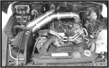
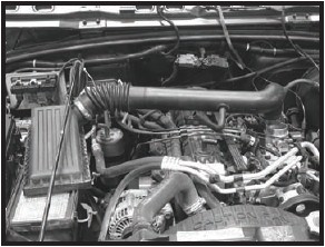
Step 2: Loosen clamp at throttle body. Remove the crank case vent hose from 90° fitting. If present, disconnect the IAT electrical connector. Unclip air box cover. Lift entire assembly from engine.
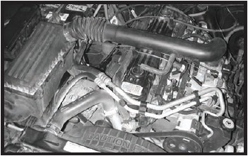
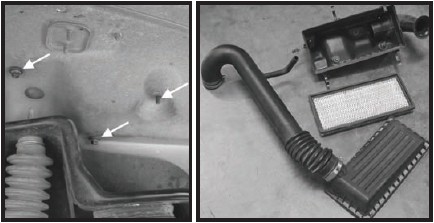
Step 3: Remove the air filter and locate the three mounting nuts on the inside of the fender well. Remove the nuts and remove the air box base from the engine compartment. The pictured components will now be out of the engine compartment.
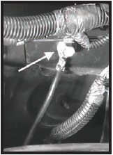
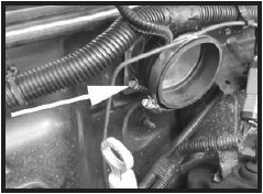
Step 4: Follow the negative battery cable to where it mounts to the firewall and remove the bolt.
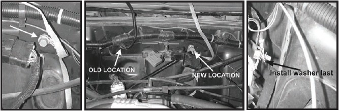
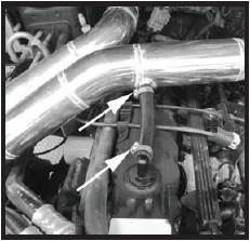
Step 5: Remove cable from the factory harness by cutting the tape on the wire sheath and sliding it out. Install the supplied convoluted tubing over the cable. Locate the pictured bolt, just to the left of the two wire harness plugs and remove it. Route the cable behind the cylinder head. Install the bolt as shown in the picture with the star washer between the body and the negative cable. Tighten the bolt.
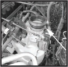
Step 6: Install the reducer coupler on the throttle body and secure the boot in place. Install a second clamp but do not tighten at this time.
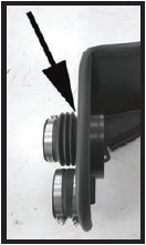
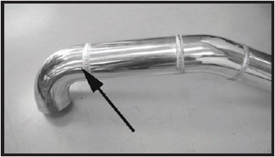
Step 7: Install the 1/16” edge in area shown with the arrow. This may require trimming to the correct length. Install the edge trim around the edge of the heat shield. This may require trimming to the correct length.
Step 8: Place the velocity stack adapter in the heat shield and install the supplied flex coupler making sure the coupler is pushed completely against the heat shield. Once the adapter and coupler are tight against the heat shield, tighten the clamp. Install the 3” coupler and two clamps completely over the tube that is welded onto the heat shield.
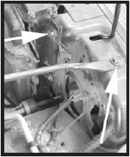
Step 9: Remove the upper radiator bolt and the strut brace bolt. These will be reused in the next step.
Step 10: Install the heat shield making sure to place the strut thru the cut out in the heat shield. Once in place, fasten it securely in place with the supplied hardware and the hardware that was removed in Step 9.
Step 11: If your vehicle came with an IAT sensor, you will need to drill a hole in the intake to install it. Remove the sensor from the stock intake tube and remove the o-ring from the sensor. Determine the best location for the sensor in the area shown in the picture, making sure that it will not interfere with any other components and the wiring harness will reach. Drill a ¾” hole at the marked location (remove all burrs and clean out any metal shavings before continuing.) Install the supplied grommet and insert the IAT sensor.
Step 12: Install the intake tube and once in desired position fasten it securely in place. If the vehicle has an IAT sensor, reconnect the sensor at this time.

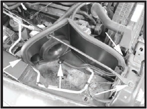
Step 13: Install the air duct tube with the firewall mount on the end of the tube. Hold the air duct tube up as high as possible against the cowl rubber molding. Ensure that the bottom of the mount is higher than the bend in the firewall, which is the base of the cowl area. Mark along the edges of the duct mount so that you can replace it in the next step without the intake tube in place. DO NOT CUT INTO THE AREA BELOW THE BEND!
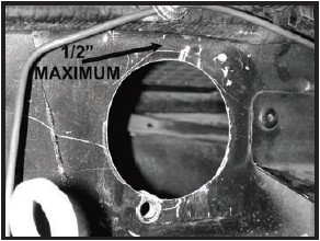
Step 14: With your duct mount located with the marker, you can take the assembled intake tube off of the vehicle for now. At this point mark the center of the mount to locate the 3” hole. Before drilling, make sure the top of the hole will be no more than 1/2” below the cowl molding. Find the center of your 3” hole for your hole saw so that you drill in the proper place. MAKE SURE THE TOP OF THE HOLE WILL BE NO MORE THAN 1/2” BELOW THE COWL MOLDING.
Step 15: In this step, you will be using a 3” hole saw to make a hole in the firewall for the fresh air source. AGAIN, VERIFY THAT THE TOP OF THE HOLE WILL BE NO MORE THAN 1/2” BELOW THE COWL MOLDING. Move and secure all wiring away from this area. A bungee cord can be used to keep the wiring away from the area to be drilled. If it helps, you can remove the cowling at the base of the windshield to see where you will be drilling. DO NOT CUT OR DRILL INTO THE AREA BELOW THE BEND OF THE COWL. Using the mark you made from the previous step, drill through the firewall into the cowl area. Use care and remove the piece of firewall as the edges are HOT AND VERY SHARP! NOTE: For later model years the firewall is slightly different than shown in the pictures. Also, the wire harness bracket may differ from the one in the pictures and you may have to trim, bend or move this bracket to clear the intake tube once it is in place.
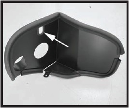
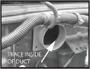
Step 16: Install the supplied firewall duct mount and once it’s in place, secure with the four supplied self-tapping screws.
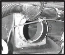
Step 17: Install the supplied coupler on the firewall duct mount and secure with supplied clamp. Install a second clamp but do not tighten it at this time.
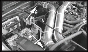
Step 18: Install the air duct tube into the firewall duct mount coupler first then align it with the heat shield. Slide the coupler on the heat shield end onto to the air duct tube making sure to equally space the coupler on the air duct tube and heat shield tube.
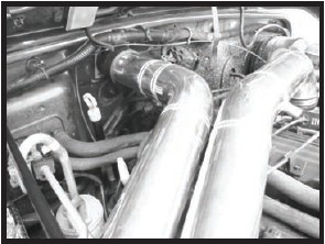
Step 19: Install the supplied crank case vent hose and fasten it securely in place.
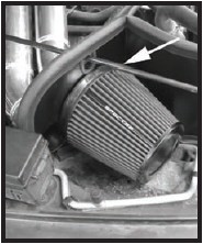
Step 20: Install the filter and securely fasten to the velocity stack adaptor.
Step 21: Make sure that all clamps and hardware are fully tightened. Reconnect the battery cable, start the vehicle and let it warm up. Shut off and inspect the installation once more for any loose clamps, wires, or hardware. Test drive & enjoy! Your installation is now complete. Periodically check all clamps and brackets.shield end onto to the air duct tube making sure to equally space the coupler on the air duct tube and heat shield tube.