 FREE 1 to 3-Day Delivery on Orders $149+ Details

How to Install Snyper Tubular Fender Flares - Textured Black (07-17 Wrangler JK) on your Jeep Wrangler
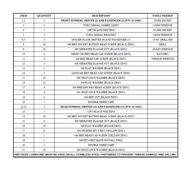
Tools Required
- 13MM SOCKET
- 13MM WRENCH
- 10 MM SOCKET
- 10MM WRENCH
- 25/64” DRILL BIT
- DRILL
- ALLEN WRENCH
- RATCHET
- TORQUE WRENCH

Shop Parts in this Guide
CARE INSTRUCTIONS
REGULAR WAXING IS RECOMMENDED. DO NOT USE ANY TYPE OF POLISH OR WAX THAT MAY CONTAIN ABRASIVES.
STAINLESS STEEL PRODUCTS CAN BE CLEANED WITH MILD SOAP AND WATER. STAINLESS STEEL POLISH SHOULD BE USED TO POLISH SMALL SCRATCHES.
GLOSS BLACK FINISHES SHOULD BE CLEANED WITH MILD SOAP AND WATER.
PROCEDURE
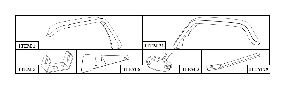
1. Remove contents from box, verify if all parts listed are present and free from damage.
Carefully read and understand all instructions before attempting installation.
Failure to identify damage before installation could lead to a rejection of any claim.
Front Fender Installation:
2. Starting on either side. Reach inside the front factory fender flare and disconnect the outer signal wiring harness.
3. Along the inner fender remove the factory M10 bolts. Once the inner fender plastic is loose, carefully pull the outer fender flare off.
4. Remove any plastic clips that are still attached to the vehicle. Note: Clean fender area if needed.
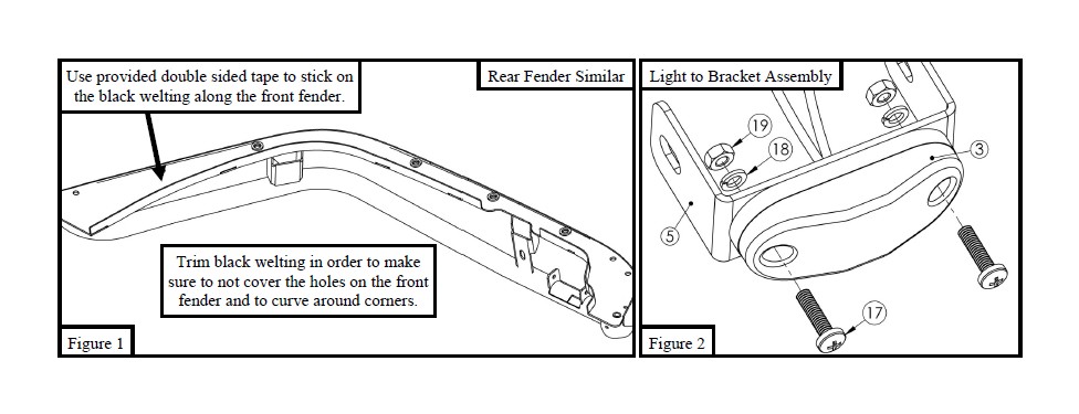
5. Locate (1) Front Fender (Item 1/2), Black Welting (Item 4) and Double Sided Tape (Item 20). Along the outer front fender use the double sided tape to stick the black welting onto the front fender. See Figure 1. Note: Trim welting to make sure that holes along the fender are not covered. The welting will require triangles to be cut into the flat portion to allow it to flex around the corners.
6. Locate (1) Turn Signal Bracket and (1) Turn Signal Amber Light and secure together using provided M4 hardware (Items 17 - 19). See Figure 2.
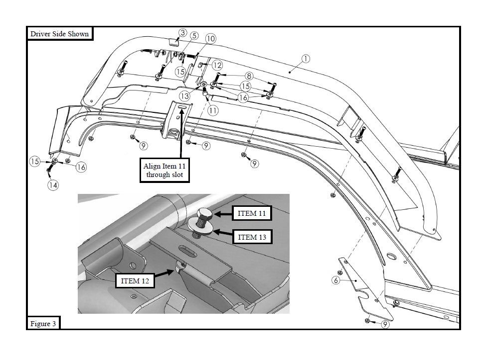
7. Align Front Fender with the vehicles fender area and loosely secure using the provided M6 and M8 hardware. Refer to Figure 3.
8. Align and adjust Front Fender as needed and then tighten hardware: M8 to 17 ft-lbs and M6 to 10 ft-lbs.
9. Repeat Steps 2 - 8 for opposite side.
10. On both front fenders connect the Turn Signal Amber Light with the vehicle wire harness. Solder or use butt connectors to connect wires.
11. Trim the factory inner fender and tuck it behind the welded lip on the Westin Fenders. Use factory hardware to secure.
Rear Fender Installation:
2. Starting on either side of vehicle. Remove plastic clips along the inner factory fender. Once all of the plastic clips are re-moved, carefully pull the factory fender flare off.
3. Remove any plastic clips that are still attached to the vehicle. Note: Clean fender area if needed.
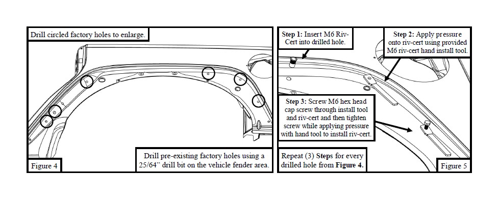
4. Drill the pre-existing holes along the vehicle fender area to prepare them for riv-certs. Use a 25/64” drill bit. See Figure 4. Note: Holes accessible from the rear do not need to be drilled.
5. Locate the provided M6 Riv-Cert Hand Install Tool (Item 29), (6) M6 Riv-Certs (Item 27), and (1) M6 hex head cap screw (Item 28). Install the M6 Riv-Certs onto the vehicle fender in the previously drilled factory holes using the M6 Riv-Cert Hand Install Tool and M6 hex head cap screw. Refer to Figure 5. Note: Do not attempt to use the button head bolts for this; they may strip.
6. Locate (1) Rear Fender (Item 21/22), Black Welting (Item 23) and Double Sided Tape (Item 30). Along the outer rear fender use the double sided tape to stick the black welting. Refer to Figure 1. Note: Trim welting to make sure that holes along the fender are not covered. The welting will require triangles to be cut into the flat portion to allow it to flex around the corners.
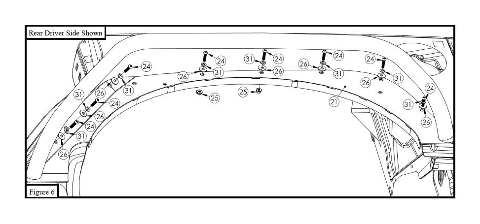
7. Align Rear Fender with the vehicles fender area and loosely secure using the provided M6 hardware. Refer to Figure 6.
8. Align and adjust Rear Fender as needed and then tighten hardware: M6 to 12 ft-lbs.
9. Repeat Steps 2 - 8 for opposite side.
Failure to follow these instructions could lead to death, personal injury, and / or property damage.
FASTENERS: All Westin supplied fasteners must be utilized and installed in accordance with the installation in-structions and apply torque to the specifications as defined. DOUBLE CHECK ALL FASTENERS BEFORE INITIAL USE, AND PERIODICALLY IN THE FUTURE TO ENSURE PROPER FUNCTION AND SAFETY.
DRILLING: Most Westin products do not require drilling for installation. If drilling is defined as required, use caution when drilling a vehicle. FAILURE TO REVIEW AN AREA TO BE DRILLED MAY RESULT IN PERSONAL INJURY AND/OR INJURY TO OTHERS AS WELL AS VEHICLE DAMAGE.
EYE PROTECTION: ALWAYS WEAR SAFETY GLASSES OR GOGGLES DURING THE INSTALLATION PROCESS TO AVOID PERSONAL INJURY.
MAXIMUM TOWING/CARRYING CAPACITY: The Westin Receiver Hitches will have a visible tow rating label affixed directly on the product. Us-er should never exceed the vehicle manufacturers maximum tow and weight rating regardless of the capacity of the hitch. FAILURE TO FOLLOW THESE GUIDELINES WILL VOID THE WESTIN WARRANTY AND MAY RESULT IN PERSONAL INJURY AND/OR INJURY TO OTHERS AS WELL AS VEHICLE DAMAGE.
