 FREE 1 to 3-Day Delivery on Orders $149+ Details

How to Install Smittybilt XRC Gen2 Rear Bumper (18-19 Jeep Wrangler JL) on your Jeep Wrangler
Installation Time
2 hours
Tools Required
- Trim Removal Tool
- Ratchet (1/4” and 1/2”)
- Sockets (8, 16 and 21 MM)
- Wrench (18mm)
- Help from a friend

Shop Parts in this Guide
Note: Park the vehicle on a safe and leveled surface and wear protection gear.
Installation Instructions:
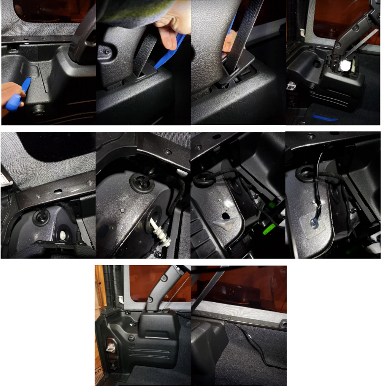
1. Using an 8 MM socket, remove the inner plastic covers behind the two corners of the factory bumper (passenger’s side shown). There are a total of three screws on each side.
2. Using a 16 MM socket, remove the side rear corner brackets. There are a total of four bolts holding each of the two brackets (passenger’s side shown).
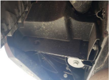
3. Depending on the options package in your vehicle you might have to remove:
a. the trailer plug and bracket (16 MM Socket)
b. the four 18 MM bolts holding the receiver hitch to the frame cross member.
c. The two 16 MM bolts holding the bumper to bottom of the frame cross member.
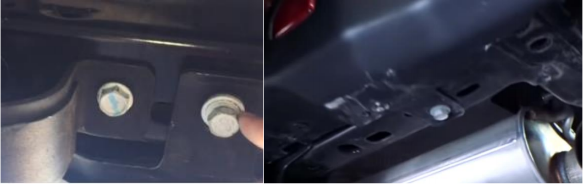
c. The two 16 MM bolts holding the bumper to bottom of the frame cross member.
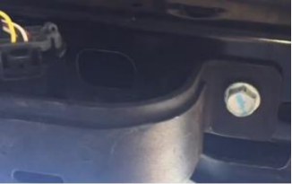
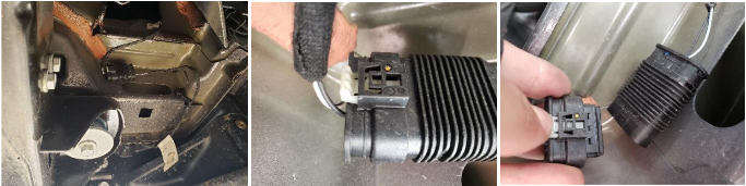
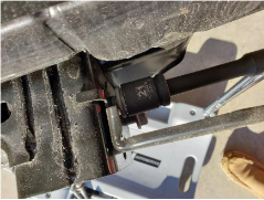
4. Disconnect the plug for the license plate and back up sensors on the driver’s side. To do so, pull back the white insert, press it and pull the plug.
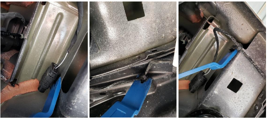
5. Using the trim removal tool, detach the three Christmas tree type pins holding the wiring harness to the frame.
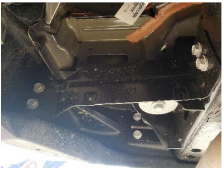
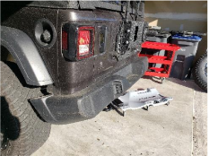
6. Now remove the four 16 MM bolts holding the factory bumper. Both passenger and driver sides are shown below.
7. Now the factory bumper is loose and can be pulled back and removed.
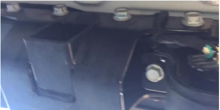
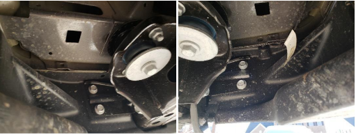
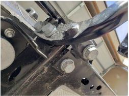
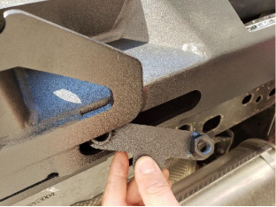
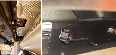
8. With a 21mm socket, remove the bolts holding the bumper bracket to the frame.
9. If equipped, remove the four 21 MM bolts holding the factory tow hook to the frame.
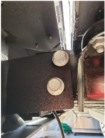
10. If equipped, remove the back-up sensors from the factory bumper. Note the positon of each sensor as you will need to reinstall in the same location on the new bumper.
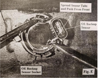
To remove the sensors, use a picker or a screwdriver to remove the sensor socket, spread the sensor tabs and push the sensor from the outside. Try not to break or lose the sensor’s O-rings. Those will be reused.
On Rubicon models, disengage the locking tabs securing the outer retaining ring to the socket. Push the sockets out from the back side and remove from the factory rear bumper. Note the orientation of the back-up sensor retainers in the factory bumper prior to removal for reinstallation.
11. If equipped, install the previously remove factory back-up sensors into the factory sensor sockets and insert in the new bumper. Secure with the factory retainers.
12. On vehicles without back-up sensors, install the block-off plugs.
13. Using a 10mm wrench, install the provided 6” led light bars to the lights mounting brackets.
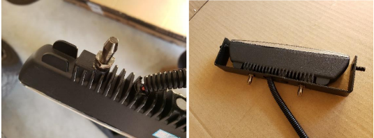
14. Install the light brackets to the new bumper.
15. With the help of someone else, raise the bumper against the frame rails and align the mounting holes. Loosely secure to the outer frame rails using the previously removed factory screws.
Different from the factory bumper, you will not be able to rest the new bumper on the frame while attaching with the hardware. You will have to hold it in place until, at least, one bolt have been placed on each side.
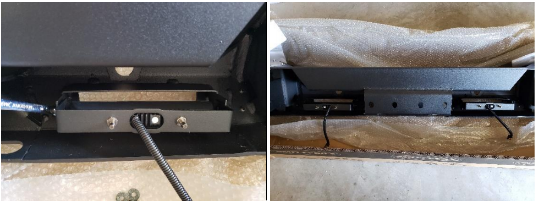
16. Insert the provided nut plates into the center holes in the bottom of the center of the bumper.
17. Secure the rear bumper to the rear frame crossmember using the four supplied 12m x 100mm bolts, washers and nut plates installed in the previous step.
18. Level the bumper and torque the 12mm bolts to 80 ft./lbs.
19. Torque the bolts on the outer frame rails to 65 ft./lbs.
20. You can either wire the led lights to a switch in the dash or into the factory reverse light circuit. If the later, the manufacturer recommends that this task is performed by a qualified automotive electrician. Every build is unique and there are many ways to run the wiring and install the on/off switch. You should consider among other things the other electronics in your build (current and future) and then plan how to route the wires.
Some guiding principles should be followed as follows:
a. Plan ahead where the on/off switch will be mounted.
b. Route the harness to the mounting location but don’t secure (e.g. zip-tie) until all connections have been performed.
c. Avoid sharp edges, abrasive surfaces and heat sources.
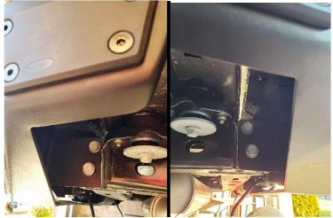
21. There are two firewalls on the JL. The easier to access is the one the driver’s side (shown below). The one on the passenger’s side is more difficult to access as it sits in about the same area but is covered by the back-up battery. The first pic below shows the firewall in the driver’s side from the engine bay and the second picture from the inside of the vehicle.
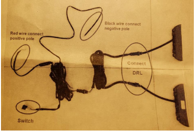
22. See the wiring diagram below.
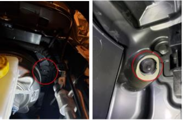
23. Below are some pics of a sample wiring. In this case, the cable is being routed using a factory hole on the body of the Jeep, where the rear driver’s brake light is mounted.
Routing the cable to the front
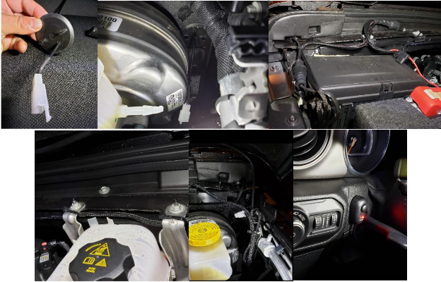
Inside the hood and cabin
Installation Instructions Written by ExtremeTerrain Customer Duamel Santiago 1/7/2019
