 FREE 1 to 3-Day Delivery on Orders $149+ Details

How to Install SkyJacker 6-7 in. Long Arm Suspension Lift Kit w/ Shocks (07-17 Wrangler JK) on your Jeep Wrangler
Installation Time
1 days
Tools Required
- Safety Glasses
- Metric / Standard Wrenches & Sockets
- Allen Wrenches
- Drill & Assorted Drill Bits
- Grinder / Cut Off Wheel
- Pipe Wrench
- Floor Jack
- Jack Stands
- Measuring Tape
- Torque Wrench
Before beginning the installation, thoroughly & completely read these instructions & the enclosed driver’s WARNING NOTICE. Affix the WARNING decal in the passenger compartment in clear view of all occupants. Please refer to the Parts List to insure that all parts & hardware are received prior to the disassembly of the vehicle. If any parts or hardware are found to be missing, contact SKYJACKER® Customer Service at 318-388-0816 to obtain the needed items. If you have any questions or reservations about installing this product, contact SKYJACKER® Technical Assistance at 318-388-0816.
Make sure you park the vehicle on a level concrete or asphalt surface. Many times a vehicle is not level (side-to-side) from the factory & is usually not noticed until a lift kit has been installed, which makes the difference more visible. Using a measuring tape, measure the front & rear (both sides) from the ground up to the center of the fender opening above the axle. Record this information below for future reference.
IMPORTANT NOTES:
• The draglink must be adjusted to center the steering wheel before the vehicle is driven. Failure to do so will cause computer errors, odd handling characteristics, & poor performance.
• Replacement front & rear drive shafts are recommended, contact Skyjacker for more info.
• This lift is determined from the amount of lift to the front of the vehicle, while only lifting the rear to a position level with the front.
• If larger tires (10% more than the OEM diameter) are installed, speedometer recalibration will be necessary. Contact your local Jeep dealer or an authorized dealer for details.
• After installation, a qualified alignment facility is required to align the vehicle to the OEM specifications.
Front Installation:
1. Park the vehicle on flat level ground, set the emergency brake, & block the rear tires / wheels.
2. Raise the front of the vehicle & support the frame rails using jack stands.
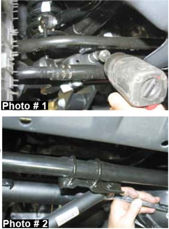
3. Disconnect the OEM front sway bar end links using a 18mm socket & disconnect the OEM front track bar from the axle using a 21mm socket. (See Photo # 1)
4. If installing a Skyjacker steering stabilizer (Part # 7003), remove the OEM steering stabilizer using a 18mm socket. (See Photo # 2)
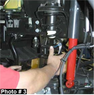
5. Disconnect the OEM front shocks using a 18mm socket. Remove the front tires / wheels & remove the OEM front coil springs. (See Photo # 3) Remove the OEM front shocks.
6. Locate the OEM lower control arm mount on the frame. Note: It will be necessary to modify these mounts to allow for the installation of the new Skyjacker lower control arm brackets. Remove the OEM automatic transmission skid plate & remove the OEM lower control arms, one side at a time.
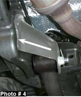
7. Using a grinder, remove the weld attaching the inner mounting plate to the frame. All that will be left is the single mounting plate under the frame. (See the Arrow in Photo # 4)
8. Using a transmission jack, support the rear of the transfer case. Disconnect the transmission from the OEM cross member. Raise the transmission / transfer case approximately 2". This will allow easier access around the exhaust to install the new Skyjacker front control arm brackets.
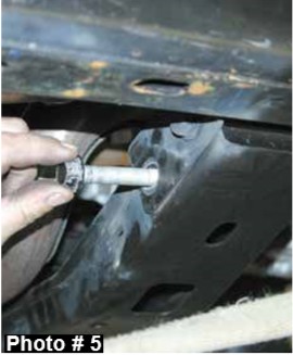
9. Remove the inner most mounting bolt on the transmission cross member using a 18mm socket. (See Photo # 5)
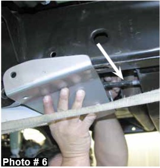
10. Place the OEM cross member bolt through the back of the new Skyjacker control arm bracket & install. (See Photo # 6)
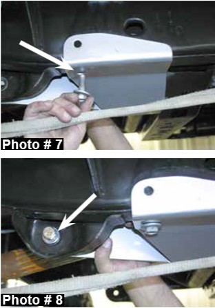
11. Install the OEM skid plate bolt that was removed in Step # 6. (See Photo # 7)
12. Install the supplied 9/16" x 1 1/2" fine thread bolt, washers, & nut at the OEM control arm position. (See Photo # 8)
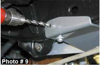
13. With all bolts tight, mark & drill the new location on the outside of the frame using a 1/2" drill bit. (See Photo # 9) Once drilled, install the supplied 1/2" x 1 1/2" fine thread bolt, washers, & nut. Note: It may be necessary to remove the lower bolt first to allow the installation of the new outer frame bolt. Note: The passenger side control arm can be installed along with the bracket. If not, it will be necessary to raise the transmission again later to install the control arm.
Note: If installing a Skyjacker front coilover kit, proceed to Step # 24 at this time.
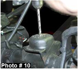
14. Locate the new Skyjacker front bump stop spacers. Place the new bump stop spacers on the center of the bump stop pads located on the front axle. Mark & drill using a 25/64" drill bit. (See Photo # 10) 6" Kits: Remove the OEM upper bump stop & reinstall the new Skyjacker poly bump stop.
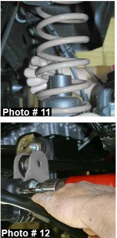
15. Place the new bump stop spacers inside the new Skyjacker coil springs & install the new coil springs. Attach the new bump stop spacers to the axle using the supplied 3/8" X 4" button head bolts with one washer under each nut. (See Photo # 11)
16. Locate the OEM front track bar mount & place the new Skyjacker track bar bracket inside the OEM mount. Drill the outer OEM holes all the way through the rearward plate using a 7/16" drill bit. (See Photo # 12) Attach the new track bar bracket at the outer two locations using the supplied 7/16" x 2 1/2" fine thread bolts, washers, & nuts. Attach the new track bar bracket at the OEM location using the OEM bolt. Let the weight of the frame down onto the new Skyjacker coil springs & attach the OEM track bar to the new track bar bracket using the supplied 14 x 80mm bolt, washers, & nut.
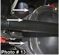
17. Remove the three OEM upper left differential cover bolts. (See Photo # 13)
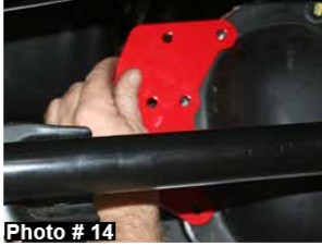
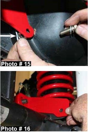
18. Hold the new Skyjacker differential bracket (D30 or D44) up to the differential. (See Photo # 14) Place the supplied thick 5/16" washers between the new differential bracket & differential. (See Arrow in Photo # 15) Attach using the supplied 5/16" x 1" coarse thread bolts, flat washers, & lock washers. (See Photo # 15) Note: Do not tighten at this time.
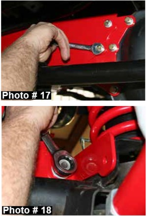
19. Attach the new Skyjacker rear brace to the upper rear mounting bolt of the new track bar bracket. (See Photo # 16)
20. Install the new Skyjacker support brace between the new differential bracket & rear mounting bolt of the new track bar bracket using the OEM 14mm hardware & supplied 5/16" x 1" fine thread bolts, flat washers, & nuts. (See Photo # 17 & # 18) Note: Do not tighten at this time.
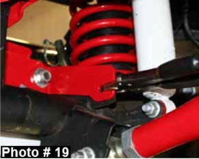
21. Clamp the new rear brace to the OEM spring perch & drill through the new rear brace & OEM spring perch using a 7/16” drill bit. Install the supplied 7/16" x 1” fine thread bolt, washers, & nut to the spring perch & tighten at this time. (See Photo # 19)
22. Once the 7/16" hardware has been tightened, complete the install by tightening all remaining 14mm & 5/16" hardware.
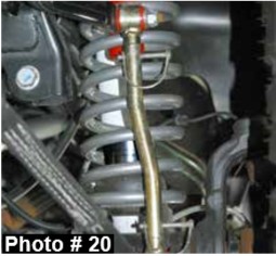
23. Assemble the new Skyjacker sway bar end links using the supplied steel sleeves. Attach the eyes using the supplied 1/4" snap pins. Attach the new sway bar end links to the axle using the OEM hardware. Attach to the OEM sway bar using the supplied 1/2" x 2 1/2" button head bolt & use one large USS washer under each nut. (See Photo # 20)
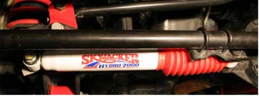
24. If installing a new Skyjacker steering stabilizer (Part # 7003), install at this time. (See Photo Below).
26. The recommended pre-set length of the new Skyjacker control arms are as follows:
4” Measurements
Lower Front should be set @ 31 1/4”
Lower Rear should be set @ 34 7/8”
Upper Front should be set @ 18 3/8”
Upper Rear should be set @ 18”
6” Measurements
Lower Front should be set @ 32”
Lower Rear should be set @ 35”
Upper Front should be set @ 18 3/4”
Upper Rear should be set @ 18 1/16”
The final length will need to be set by a qualified alignment facility.
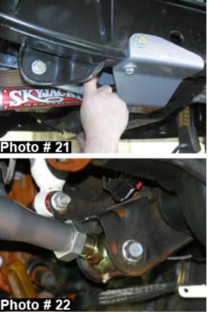
27. Install the new lower control arms using the OEM hardware. (See Photo # 21 & # 22) Install the new lower control arms with the bend up & towards the middle of the vehicle. Once installed, tighten the jam nut. Be sure that once tightened, the rod end sits square inside the mount. With the new lower control arms installed, lower the transmission & re-attach to the OEM cross-member.
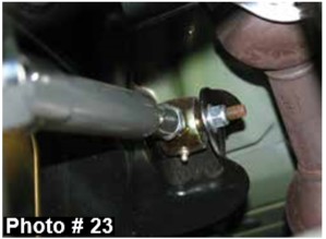
28. With the new lower control arms installed, remove the OEM upper arms. It will be necessary to cut off the OEM bolt at the frame due to it hitting the exhaust when trying to remove. Install the new Skyjacker upper control arms using the same process as the lower. Install using the supplied 12mm I.D. bolt inserts. Attach to the frame using the supplied 12mm x 80mm bolts, washers, & nuts. (See Photo # 23)
Note: If installing a Skyjacker front coil-over kit, proceed to Step # 31 at this time.
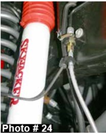
29. 6" Kits: Remove the OEM front brakelines & install the new Skyjacker stainless steel braided lines. Attach to the frame using the supplied 90 degree brackets & OEM hardware. (See Photo # 24) Install the new Skyjacker front shocks.
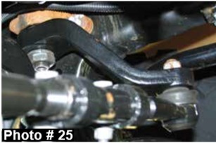
30. Disconnect the OEM drag link from the OEM pitman arm. Using a pitman arm puller, remove the OEM pitman arm & install the new Skyjacker pitman arm. (See Photo # 25) Install the front tires / wheels & lower the vehicle to the ground.
Rear Installation:
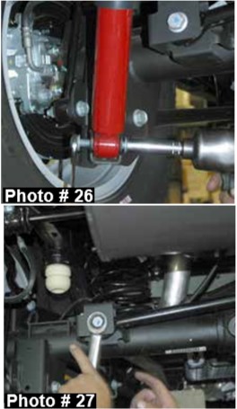
31. Block the front tires / wheels, raise the rear of the vehicle, & properly support the frame rails using jack stands. Remove the OEM rear shocks using a 16mm socket. (See Photo # 26)
32. Disconnect the OEM rear track bar from the axle using a 21mm socket. (See Photo # 27) Disconnect the OEM rear sway bar end links using a 18mm socket.
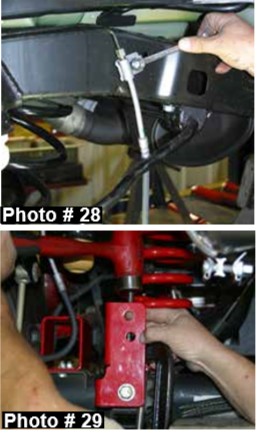
33. Disconnect the OEM ABS line & brake line from the frame. (See Photo # 28) Lower the axle down & remove the OEM rear coil springs.
34. Place the new Skyjacker rear track bar bracket over the OEM track bar bracket on the axle. With the new track bar bracket seated flush, clamp the new track bar bracket in place (mark using a center punch) & drill the new center mounting holes using a 15/32" drill bit. (See Photo # 29)
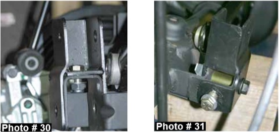
35. Install the supplied 7/16" x 1" fine thread bolt & nut. Use one 7/16" washer under the nut. (See Photo # 30)
36. It will be necessary to drill through the driver side bottom of the OEM bracket & through the new Skyjacker track bar bracket. Drill using a 17/32" drill bit. Once drilled, install the supplied 1/2" x 1 1/4" fine thread bolt & nut. Use one washer under the bolt. Install the supplied 9/16" x 3 1/2" bolt, washers, & nut at the bottom location being sure to use the supplied crush sleeve. (See Arrow in Photo # 31)
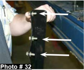
37. Remove the three OEM upper left differential cover bolts. (See Photo # 32)
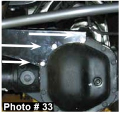
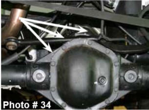
38. Attach the new Skyjacker track bar brace to the differential using the supplied 5/16 x 1" coarse thread bolts. Do not tighten at this time. The end of the new bracket should be between the new Skyjacker track bar bracket & the new coil spring. Use the supplied thick gold plated 5/16" washer between the bracket & the differential cover. Use a supplied 5/16" lock washer under the head of each bolt. (See Photo # 33 & # 34) Do not tighten at this time.
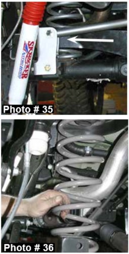
39. Attach the new brace to the front side of the new track bar bracket between the bracket & the new coil spring. Do not tighten at this time. (See Photo # 35)
40. Torque the 5/16" bolts at the differential & the 14mm bolt on the track bar to OEM specifications.
41. 6" Kits: Remove the OEM upper bump stops & install the new Skyjacker bump stops. Install the new Skyjacker Softride® rear coils. (See Photo # 36) Be sure to re-use the upper OEM rubber isolator pad.
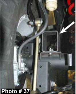
42. Attach the new Skyjacker rear bump stop brackets to the OEM location on the axle using the supplied 5/16" x 1" fine thread bolts, washers, & nuts. (See Photo # 37) Be sure to install the new bump stop brackets so the angled end is towards the rear of the vehicle.
43. Let the weight of the vehicle onto the new coil springs. Install the new Skyjacker sway bar end links using the supplied 5/8" hourglass bushings & steel sleeves. Attach using the supplied 1/2" x 2 1/2" button head bolts & nuts. One large USS washer will be used under the head of each bolt with the smaller SAE washer under the nut. (See Photo # 37)
44. Attach the OEM track bar to the new track bar bracket using the supplied 9/16" x 3" fine thread bolt, washer, & nut. See the included track bar brace & instructions at this time. 4" Kits: Be sure to use the upper mounting location on the new Skyjacker track bar bracket. One washer will be used under the head of the bolt. Be sure to install the bolt from the front side toward the rear.
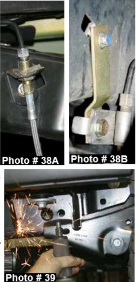
45. 6" Kits: Remove the OEM rear brakelines & install the new Skyjacker brake lines. Install using the supplied 90 degree bracket. The new bracket will attach to the OEM location on the frame using the OEM hardware. (See Photo # 38A) 4" Kits: Will relocate the OEM brake line on the frame using the supplied brackets & 1/4" hardware. Position the brackets so the bend is under the frame. Make sure there is space between the hard brake line & the frame rail. (See Photo # 38B)
46. Remove the OEM driver side lower control arm & disconnect the exhaust behind the catalytic converter. Note: It will be necessary to disconnect the exhaust hangers to allow for drilling of the mounting hole inside the frame rail.
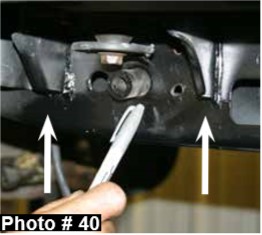
47. Using a cut off wheel, cut the welds that attach the OEM lower control arm brackets to the frame & remove 1" from the bottom of each side of the body mount bracket. (See Photo # 39 & Arrows # 40) Once removed, grind the frame smooth.
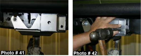
48. Locate the new Skyjacker lower control arm brackets & crush sleeves. Install the crush sleeve at the OEM location in the frame. (See Photo # 41)
49. Install the new control arm bracket on the driver side using the supplied 1/2" x 4 1/2" fine thread bolt, washers, & nut. (See Photo # 41)
50. With the new control arm bracket seated flush against the frame rail, mark the front mounting locations on both the inside & outside of frame rail. (See Photo # 42)
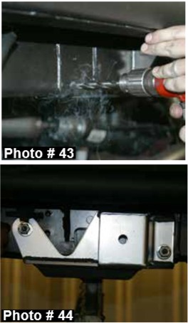
51. Lower the new control arm bracket & drill the mounting location from each side of the frame rail using a 1/2" drill bit. (See Photo # 43)
52. Once drilled, install the supplied 1/2" x 4 1/2" fine thread bolt, washers, & nut. (See Photo # 44)
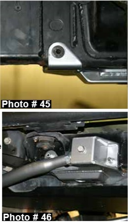
53. Repeat this process on the passenger side. Note: It will be necessary to disconnect the drive shaft & remove the fuel tank to allow access to the frame. Attach the passenger side bracket using the supplied 1/2" x 4" counter sunk bolt for mounting the rear of the new bracket & the supplied 1/2" x 4 1/2" counter sunk bolt for mounting the front of the new bracket. The bolts will install from the inside of the frame rail. (See Photo # 45) Use one washer & nut on the outside of the frame. Once installed, reinstall the fuel tank & drive shaft.
54. Install the new Skyjacker lower control arms using the same process as the front arms. (Install the new lower control arms with the rod end towards the outside of the vehicle.) (See Photo # 46)
55. Remove the OEM upper rear control arms & install the new Skyjacker upper rear control arms. (Install the new upper control arms with the rod end towards the outside of the vehicle.)
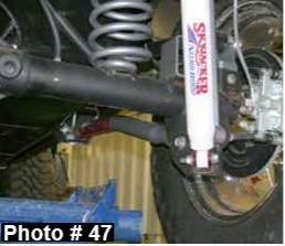
56. Install the new Skyjacker rear shocks, rear tires / wheels, & lower the vehicle to the ground. (See Photo # 47)
FINAL NOTES:
• The draglink must be adjusted to center the steering wheel before the vehicle is driven. Failure to do so will cause computer errors, odd handling characteristics, & poor performance.
• After the installation is complete, double check that all nuts & bolts are tight. Refer to the following chart for the proper torque specifications. (Do not retighten the nuts & bolts where thread lock compound was used.)
• With the vehicle placed on the ground, cycle the steering lock to lock & inspect the steering, suspension, brake lines, front & rear drivelines, fuel lines, & wiring harnesses for proper operation, tightness, & adequate clearance.
• Have the headlights readjusted to the proper settings.
• Have a qualified alignment center align the vehicle to the OEM specifications.
• After the first 100 miles, check all hardware for the proper torque & periodically thereafter.
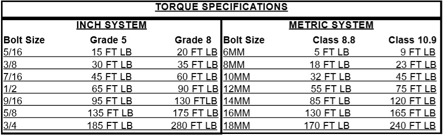
The above specifications are not to be used when the bolt is being installed with a bushing.

