 FREE 1 to 3-Day Delivery on Orders $149+ Details

How to Install Rugged Ridge Chrome Mirrors Dual Focal w/ LED Lights, Pair on your Wrangler

Shop Parts in this Guide
Introduction
This mirror kit is designed to enhance the appearance of your Jeep. This kit can be used on all Wranglers, with half and full doors. Some models may require upper door hinges that are machined to accept the mirrors. The mirrors can be wired to operate with vehicle turn and/or parking lights. Installation and wiring processes may vary slightly based upon the model, year, and door type.
Figure 1 Kit includes one each of RIGHT and LEFT mirrors, all required wiring and hardware.
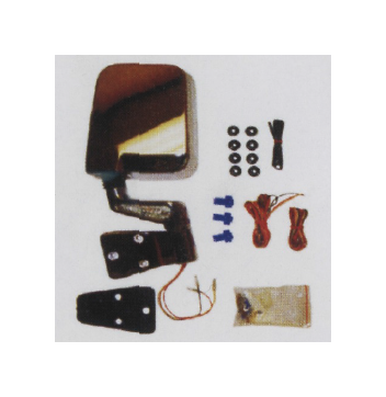
Contents
Right Mirror Assembly Black or Chrome
Left Mirror Assembly Black or Chrome
Hardware Package Includes mounting hardware, wiring and
connectors.
Procedure
The appearance, performance and durability of the installation of these mirrors will be determined by the work quality of the installer. The proper tools, a basic level of understanding and skill, and a shop manual or wiring diagram will be beneficial.
Mirror Installation
The mirror assembles bolt directly to the upper door hinges on half and full doors utilizing the same hole locations that held the OE mirrors. The mirrors can be installed on other models either by drilling and tapping the upper door hinges or installing a pair of upper door hinges that are already machined to accept mirrors. The kit can be installed in a number of possible mounting and wiring configurations, some more involved than others. The following installation was performed on a 1990 YJ
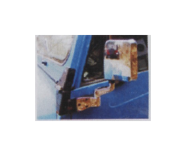
Figure 2. There is no exposed wiring on the outside of the vehicle. This requires drilling holes in the doors and routing wires through the doors. Less exposed wiring provides a cleaner look with less chance of snags.
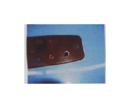
Figure 2 is of an installation that requires drilling several holes in each door. A no-drill installation is also possible if desired. A significant amount of wiring will be exposed though.
Figure 3. The first hole needs to be drilled in this location through the hinge and outer door.
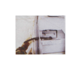
Figure 4. This cut-away of a door shows the required location of the second hole. It was necessary to locate the hole nearer the inside of the door to avoid hitting the lower section of the window channel. The wire loom shows the desired wire routing.
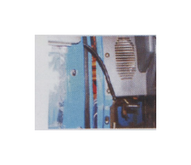
Figure 5. The wires and loom can then be pulled through the door, and the mirror fastened to the door. Be sure to leave the wires long enough to provide for full door movement. Then install the provided male 4-pin plug and terminals. Wiring these plugs into the system will make future door removal quick and easy.
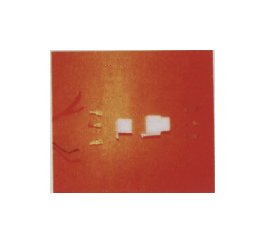
Figure 6. These are the plug assemblies. The male end is used on the mirror. The female end is used on the vehicle harness.
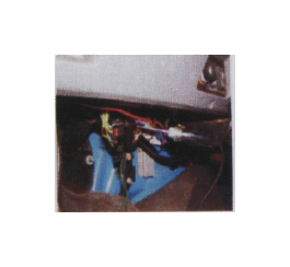
Figure 7 Locate and determine the wires needed. A wiring diagram and/or test light will be hel
Mirror Wiring
The mirror assemblies have two (2) wires that each contains two (2)
conductors.
BLACK = Ground. RED = Turn Signal. Yellow = Parking Light.
These wires need to be integrated into the vehicle wiring harness. Plugs are included to allow for easy removal of the doors. A test light and/or manual will be helpful. The 1990 YJ wiring required the parking lights to be wired into the Blue wire on the headlight switch harness. LEFT turn to be wired into the Gray/Black, RIGHT into the Brown, both on the turn signal switch harness. The colors and locations may be different on other vehicles. Use the test light to carefully test and locate the required wires.
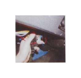
Figure 8. Use the crimp-on splice connector and spade terminal to make the wiring conn ection. The RED ( Turn ) on the left mirror is being spliced into the necessary wire on the turn signal switch harness. The same splices were done for the remaining turn, and park wires.
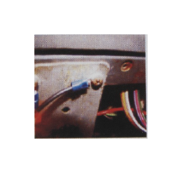
Figure 9. Terminals were crimpled onto the Black ground wires and then they were placed under existing screws in the metal dash.
Once these connections have been made the wires can he routed to the right and left sides of the vehicle: proper length can be determined, and the plugs can be installed. Make certain that both the male and female ends of the plugs arc wired to correspond correctly.
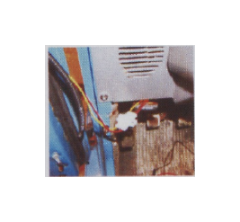
Figure 10. The final installation steps. Be sure wires correspond on both plugs. Place wiring in the loom. Tuck plugs behind dash. Test all Ii ght functions.
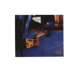
Figure 11 The initial systems checks proved that all lighting functioned properly, and our Jeepin' buddies were impressed with the cool new looks.
