 FREE 1 to 3-Day Delivery on Orders $149+ Details

How to Install Rubicon Express Leaf Spring Lift - 2.5 In., No Shocks on your 1987-1995 Wrangler
Tools Required
- Basic mechanics' tools
- Drill and 1/2’ bit
- Floor jack
- Jack stands (2 pair)
Safety Warning:
Suspension systems or components that enhance the off-road performance of your vehicle may cause it to handle differently, on and off-road, than it did from the factory. Care must be taken to prevent loss of control or vehicle rollover during sudden maneuvers. Failure to drive the vehicle safely may result in serious injury or death to driver and passengers. We recommend you always wear your seatbelt, drive safely and avoid quick turns and other sudden maneuvers. Constant maintenance is required to keep your vehicle safe. Thoroughly inspect your vehicle before and after every off-road use.
Installation Warning:
We recommend that certified technicians perform the installations of our products. Attempts to install these products without knowledge or experience may jeopardize the safety of the vehicle. These instructions only cover the installation of our products and may not include factory procedures for disassembly and reassembly of factory components. Read instructions from start to finish and be sure all parts are present before disassembling the vehicle. Included instructions are guidelines only for recommended procedures and in no way are meant to be definitive. Installer is responsible to insure a safe and controllable vehicle after performing modifications. Do not perform test drives on public roads with partially completed installations. Always double and triple check your work before use.
KIT CONTENTS:
2 RXT2210 Rear Shocks
2 RXT2611 Front Shocks
1 RE1170 Sway bar disconnect kit
4 RE1430 Leaf springs
1 RE1492 4 Leaf springs main eye bushing kit
1 RE1465 Degree shims, 2.5” x 2* aluminum* (refer to troubleshooting section)
1 RE1505 Front brake line extension
1 RE1513 Rear brake line
1 RE1630 Front track bar bracket
1 RE2100 Transfer case drop kit 1”
1 RE2420 Front u-bolt kit
1 RE2421 Rear u-bolt kit
INSTALLATION:
Note: For optimum rear driveline performance we recommend a slip yoke eliminator kit and CV drive shaft be used with this lift (see slip yoke vibration in “troubleshooting” before proceeding).
1 Block rear wheels of vehicle.
2 Raise front of vehicle and support frame with jack stands.
3 Remove front wheels.
4 Remove front shocks.
5 Remove axle end of front track bar.
6 Support axle with jack stands.
7 Remove u-bolts & spring plates.
8 Remove springs.
9 Install front brake line extensions.
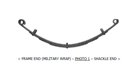
10 Lightly grease front main spring eye bushings. Main spring eyes use the 9/16” id steel sleeves at double military wrap end.
11 Install springs into vehicle with double military wrapped end at the frame (see photo 1). The center pins may come with spacers installed for use w/ floating type degree shims. Be sure pins don’t bottom out on axle tube whether using shims or not- remove spacers as required. Do not fully tighten spring eye or shackle bolts at this time.
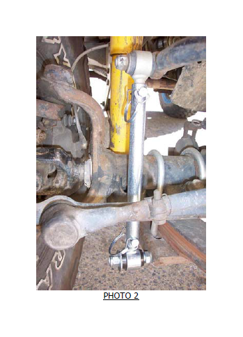
12 (See photo 2 for typical installation of steps 12-14) install new u-bolts with old spring plates. Torque u-bolts to 65-80 ft/lbs, or u-bolt specs if supplied.
13 Install longer front shocks.
14 Install sway bar disconnects.
15 Torque spring eye and shackle bolts to factory specs.
16 Install front tires.
17 Lower front of vehicle.
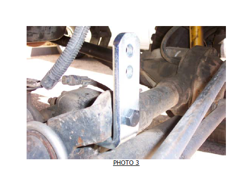
18 Install axle end of front track bar with new bracket. Small end of new bracket will fit into slot under factory mount (see photo 3). Drill out old mounting hole to ½” and attach bracket with supplied bolt. Attach track bar to bottom hole with factory bolt.
-REAR AXLE-
19 Block front wheels of vehicle.
20 Raise rear of vehicle and support frame with jack stands.
21 Remove rear wheels.
22 Support rear axle with jack stands.
23 Remove shocks.
24 Remove rear track bar. This will not be reused.
25 Remove u-bolts & spring plates.
26 Remove rear springs.
27 Remove factory rear brake hose and replace with stainless line.
28 Lightly grease and install main spring eye bushings. Main spring eyes use the 9/16” id steel sleeves at double military wrap end.
29 Install rear springs into vehicle with double military wrap end at the frame (ref photo 1). The center pins may come with spacers installed for use w/ floating type degree shims. Be sure pins don’t bottom out on axle tube whether using shims or not- remove spacers as required. If using steel Rubicon MFG’s shims, remove the spacers and replace with the shims. These steel shims will require reaming to 3/8” for 3/8” pins.
30 Do not fully tighten spring eye or shackle bolts at this time.
31 If using, insert 2* wide shim between spring and spring pad on axle. Thicker end of shim should be at front of vehicle (pinion points up).
32 Install new u-bolts with old spring plates. Torque u-bolts to 65-80 ft/lbs, or u-bolt specs if supplied.
33 Install longer rear shocks.
34 Torque spring eye and shackle bolts to factory specs.
35 If using, install transfer case drop kit by supporting one side of transfer case with floor jack. Remove hardware from one side of cross member. Install spacers and new hardware. Tighten to 55 ft/lbs. Repeat on opposite side.
36 Lower axle so that it is at full droop. Rotate the rear drive shaft to insure the yokes do not bind. If yokes bind and shims are installed properly, a slip yoke eliminator and CV drive shaft are likely required.
37 Lower rear of vehicle.
38 Bleed brake system. Inspect all brake hoses and lines for leaks, kinks or damage.
39 Grease all zerk fittings on new bushings.
40 Lengthen drag link to center steering wheel.
41 Recheck all bolts - use factory torque specs if not given. Recheck after 50 miles and then after every off road excursion.
42 Reminder: Do not reinstall the rear track bar; it will not be reused.
LIFT KIT TROUBLESHOOTING
REAR DRIVELINE:
Acceleration vibration: caused by the pinion being too high in relation to the transfer case output shaft. On leaf sprung vehicles, install axle shims to lower pinion accordingly.
Deceleration vibration: caused by the pinion being too low in relation to the transfer case output shaft. On leaf sprung vehicles, install axle shims to raise pinion accordingly.
Slip yoke vibration: caused by excessive angle at the rear transfer case slip yoke. Very common on vehicles with 2” or more of lift. The transfer case drop kit and shims provided may be an acceptable temporary fix (pinion adjustment may also be required- see acceleration and deceleration vibration troubleshooting above). If this is not acceptable, a slip yoke eliminator and CV drive shaft is likely required and highly recommended. Adjust pinion so it is 2 degrees below parallel with CV drive shaft (see acceleration and deceleration) vibration troubleshooting above). Note that transfer case drop kits can usually be omitted when using a CV drive shaft.
Note: transfer case drop kits can usually be omitted when using a CV drive shaft.
BUMP STEER:
Caused by improper relationship of drag link and track bar. A drop pitman arm matching the track bar bracket rise can help if this is a problem.

