FREE 1 to 3-Day Delivery on Orders $149+ Details

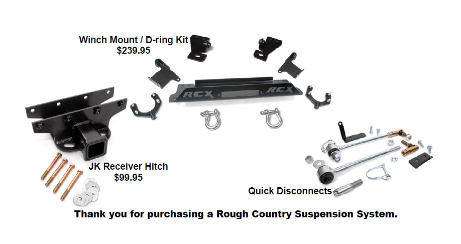
How to Install Rough Country 6 In. X-series Suspension Lift Kit on your 2007-2013 Wrangler
Tools Required
- 10mm Wrench
- 21mm Socket
- Jack
- 21mm Wrench
- Jack Stand
- Grinder
- 18mm Wrench
- 7/16" Wrench
- 13/32" Drill Bit
- 18mm Socket
- 9/16" Wrench
- Drill
- 19mm Wrench
- 9/16" Socket
- Pitman arm puller
- 19mm Deep Well Socket
- Reciprocating Saw
- 33mm Socket
- 13/16" Socket
- 7/8" Wrench

Shop Parts in this Guide
FRONT INSTALLATION INSTRUCTIONS
1. Prior to installing this kit, with the vehicle on the ground, measure the heights of your vehicle. This measurement can be recorded from the center of the wheel straight up to the top of the inner fender lip. Record the measurements.
LF:__________ ,RF:___________,
LR:__________, RR:___________
2. Place vehicle in park and chock the rear wheels. Raise the front of the vehicle with a jack and secure a jack stand beneath each frame rail behind the front control arms. Ease the frame down onto the stands.
3. Remove the front tires/wheels, using a 19mm deep well socket.
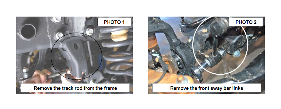
4. Using a 21mm socket, remove bolt securing the front track bar to the frame. Retain stock hardware. See Photo 1.
5. Using a 18mm socket and wrench remove the bottom sway bar bolts. Using a 21mm socket and 21mm wrench, remove the top of the sway bar link. Retain hardware for later use. See Photo 2.
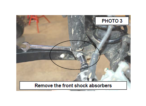
6. Remove the lower shock bolt using a 18mm socket and wrench. Using a 14mm wrench unbolt the top of the shock and remove. See Photo 3. Retain the lower stock hardware.
7. Using a 21mm socket and wrench loosen the upper and lower control arm bolts at the axle and frame, but do not remove.
8. On some models it will be necessary to remove the brake line bracket from the frame to allow the coils to be removed. Using a 10MM socket, remove the brake line bracket from the stock location.
9. Push down on the axle to allow room for the coils to be removed. Remove stock coil springs. Retain coil isolators.
10. Using a 21mm wrench, remove the bolts that secure the lower link arms to the axle.
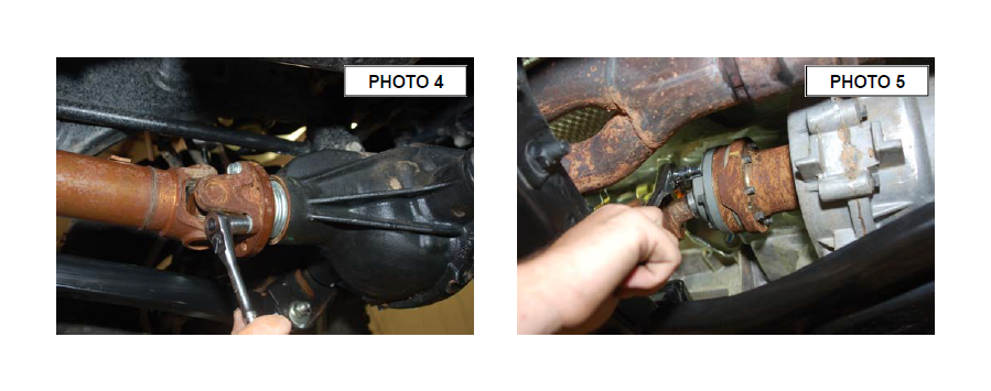
11. Remove the drive shaft from the differential using a 15mm wrench. See Photo 4.
12. Remove the driveshaft from the transfer case by removing the 8-8mm bolts as shown in Photo 5. Remove the shaft from the Jeep. Driveshaft install will be performed in a later step.
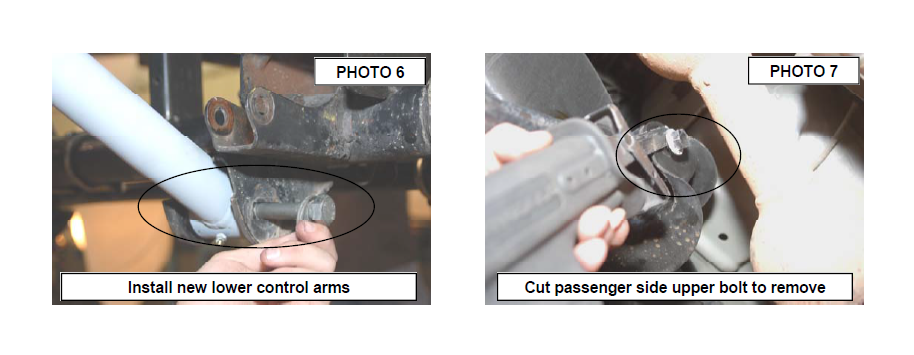
13. Assemble the lower control arms with the bushings, sleeves & adjust the arm to a length of 22 7/8” from center of hole to center of hole and tighten the jam nut using a 1 7/8” wrench. Install the adjustable heim end in the frame mount and the other end in the axle mount. Do not tighten arms in the mounts at this time. See Photo 6. The bend
on the lower control arm should be facing inward to allow for the tires to achieve full lock to lock turning.
14. Remove the bolts securing the upper control arms to the axle using a 18mm wrench/socket. It will be necessary to cut out the passenger side upper bolt as shown in Photo 7 to remove the control arm.
15. After the stock control arms have been removed assemble the bushings /sleeves in the upper control arms with the heim joints. Adjust the arms to a length of 18 3/4” from center of hole to center of hole and tighten the jam nut using a 1 1/8” wrench. Install in the heim joint in the upper mounts with supplied 12mm x 80mm bolt on the passenger side frame and stock hardware on the driver side.
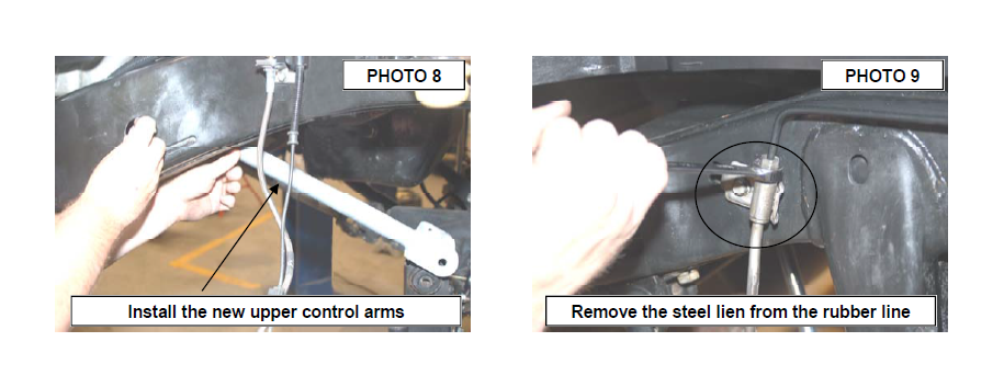
16. Install the opposite end on the axle with stock hardware. Do not fully tighten at this time. See Photo 8.
17. Loosen the stock brake line from the metal line on the frame rail shown in Photo 9 using a 12 mm line wrench. A catch pan will be needed to catch the brake fluid.
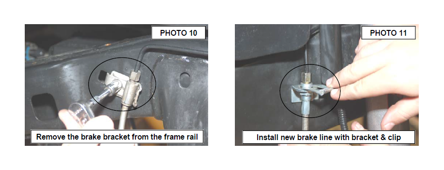
18. Remove the line from the frame rail using a 10mm socket as shown in Photo 10. Remove the brake line from the caliper and replace the brake line with the supplied stainless steel lines and brackets as shown in Photo 11. Reattach at the caliper with new supplied crush washers, tighten line and install the spring clip.
19. Install the bushings and sleeves from 1681bag2 in the shock box into the RCX shock absorber Part # 660585. Position the cup washer and stem bushing on the stem end of the shock and insert the stem in the upper shock tower. Install the remaining bushing and washer and loosely secure using the supplied nut. Tighten until the bushing swells slightly using a 9/16” wrench. NOTE: The RC 2.2 Series shocks are built to run piston down and have a built in bump stop thus a longer bump stop or bump stop extension is not needed with this kit.
20. Attach the lower end of the shock to the axle and secure using the stock hardware. Tighten to 80 ft/lbs.
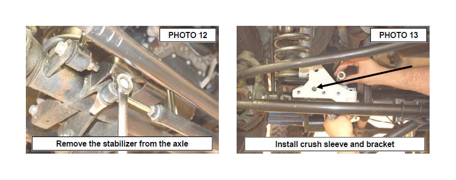
21. Remove the stock stabilizer and bracket from the axle mount using a 18mm wrench See Photo 12.
22. Install the track rod bracket as shown on the stock mount. Install the crush sleeve as shown in Photo 13.
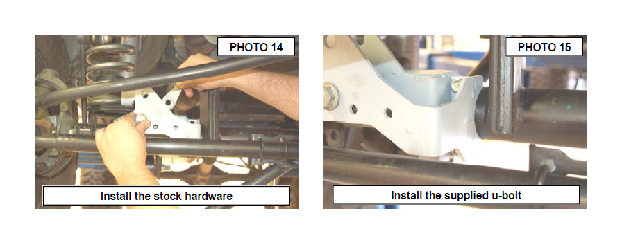
23. Install the stock hardware in the bracket as shown. See Photo 14. Do not tighten at this time.
24. Install the supplied u-bolt and nuts in the bracket as shown in Photo 15. Do not tighten at this time
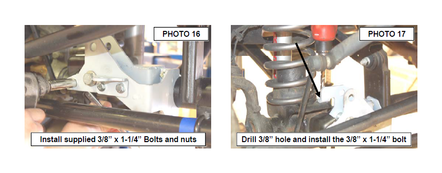
25. Install the 3/8” x 1 1/4” bolts, washer and nuts in the new bracket. If reusing the factory stabilizer the supplied bracket will install as shown with the 3– 3/8” x 1 1/4” bolts. If not installing the stock stabilizer, only two 3/8” x 1 1/4” bolts will be installed in the two far left holes in the bracket. See Photo16.
26. Drill the rear mount using a 3/8” drill bit and install the 3/8” x 1 1/4” bolt, washer and flange lock nut. See Photo 17.
27. Tighten all 3/8” hardware using a 9/16” wrench.
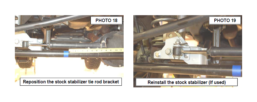
28. This next two steps will be performed if the stock stabilizer is retained. Mark the location on the factory tie rod bracket on the tie rod and loosen the u-bolt nuts using a 13mm wrench. Slide the bracket down 4” and retighten tie rod end bracket. See Photo 18.
29. Install the factory stabilizer in the new track rod / stabilizer mount with stock hardware and tighten using a 18mm socket / wrench. See Photo 19.
30. Assemble the bushings/sleeves in the track rod and adjust to a length of 32 7/8” center of hole to center of hole. Install the new track bar into stock frame bracket using the stock hardware.
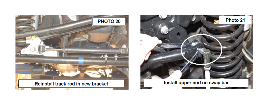
31. Check to make sure the body is centered over the axle and install the stock track bar into the new track rod bracket as shown in Photo 20 using the supplied 1/2” x 2 1/2” stock bolt/nut. Tighten using a 21mm & 22 mm socket / wrench. Torque all fasteners to specifications. It may be necessary to turn the steering wheel to align the track rod end with the axle.
32. On the front sway disconnects, assemble the supplied jam nut and end link on the sway bar link body. Adjust the sway bar to approx 11” for a 4” & 6” kit measuring end to end. Tighten the end and jam nut using a 18mm wrench.
33. Install the new sway bar link on the factory sway bar as shown in Photo 21 with the supplied 12mm Flange lock nut using a 16mm & 18mm wrench.
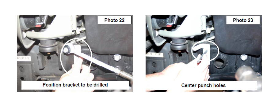
34. Install the new sway bar link on the sway bar bracket and swing up the assembly to the frame rail. See Photo 22. Remove the sway bar link from the bracket while holding the bracket in place.
35. Mark the holes to be drilled and remove the bracket from the frame. See Photo 23.
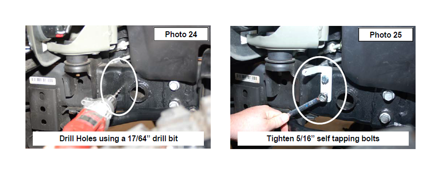
36. Drill the two holes per side using a 17/64” drill bit. See Photo 24. Be sure to only drill through outside of the frame.
37. Install the frame bracket with the supplied 5/16” self tapping bolts (2 per bracket) using a 1/2” wrench. SeePhoto 25.
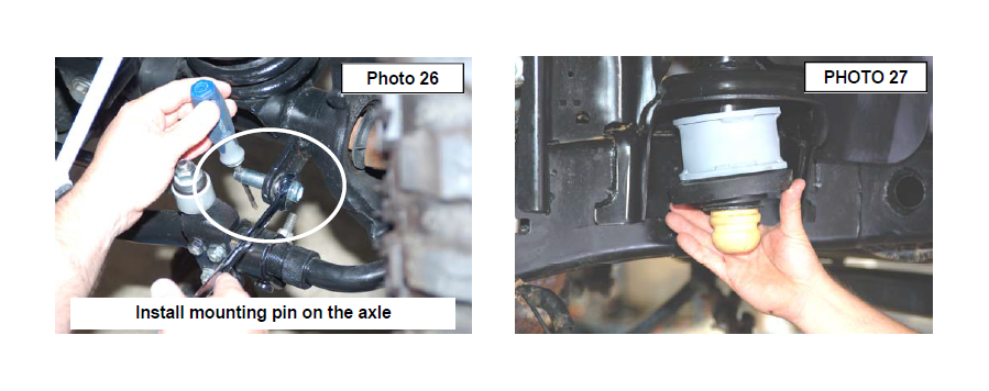
38. Install the supplied mounting pin as shown in Photo 26 and tighten using 19mm socket / wrench.
39. Install the new Rough Country coil spring spacer as shown in Photo 27 in the factory location, making sure the coil is positioned properly in the lower seat, as stock was.
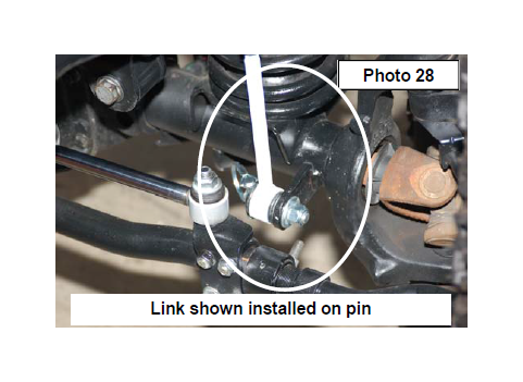
40. Swing the new sway bar link down and secure on the mounting pin using the supplied quick disconnect pin. See Photo 28.
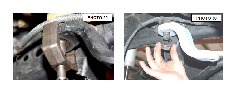
41. Using a 21mm socket remove the tie rod end from the pitman arm. Remove the pitman arm nut using a 33mm socket.
42. Using a pitman arm puller, remove factory pitman arm. See Photo 29.
43. Install the new pitman arm with the stock hardware an using a 33mm socket. See Photo 30. Reinstall the drag link on the new pitman arm with the stock nut and using a
21mm wrench.
44. Reinstall the front tires/wheels, using a 19mm deep well
socket. Lower the vehicle to the floor.
REAR INSTALLATION INSTRUCTIONS
1. Chock front wheels. Jack up the rear of the vehicle and support the vehicle with jack stands, so that the rear wheels are off the ground. Position a jack so it supports, but does not raise the rear axle.
2. Remove the rear tires/wheels, using a 19mm deep well socket.
3. Using a 21mm socket remove the track bar from the frame on the passenger side. Using a 21mm socket remove the track bar bolt at the axle and remove the track bar from the vehicle. Retain the frame side stock hardware for reuse.
4. Using a 21mm socket loosen, but do not remove the bolts securing the lower control arms at both the axle and frame.
5. On the rear of the vehicle remove the factory sway bar link using a 18mm socket and wrench on the lower. Remove the upper hardware using a 18mm wrench and a 19mm wrench on the ball joint end.
6. Using a 10mm wrench, unbolt the brake hose bracket at the frame. Retain hardware for later use.
7. Remove and discard the rear shocks using a 18mm wrench. Retain stock hardware.
8. Lower the axle enough to remove the stock coil springs.
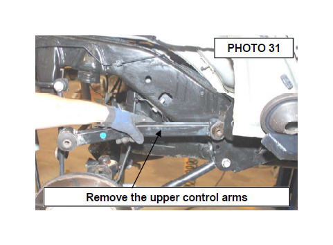
9. Remove the upper control arms from the frame and axle using a 18mm wrench. Retain the upper flag nut in the frame and all other factory hardware. See Photo 31.
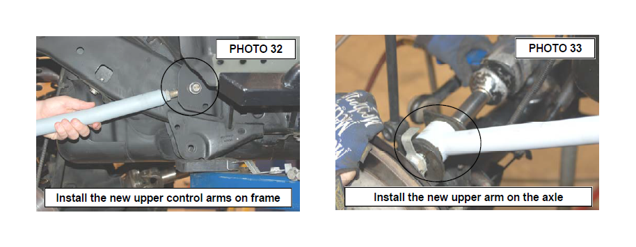
10. Assemble the bushings/sleeves in the upper control arms and heim joints. The rear upper heim joint is labeled as “Rear Upper” on the heim joint. Adjust to a length of 18 3/4” from center of hole to center of hole and tighten the jam nut using a 1 1/8” wrench. Install in the heim end on the frame with stock flag nut and the lower on the axle with
factory hardware using a 18mm wrench. See Photo 32. Photo 33 showing rear axle install. Do not fully tighten at this time.
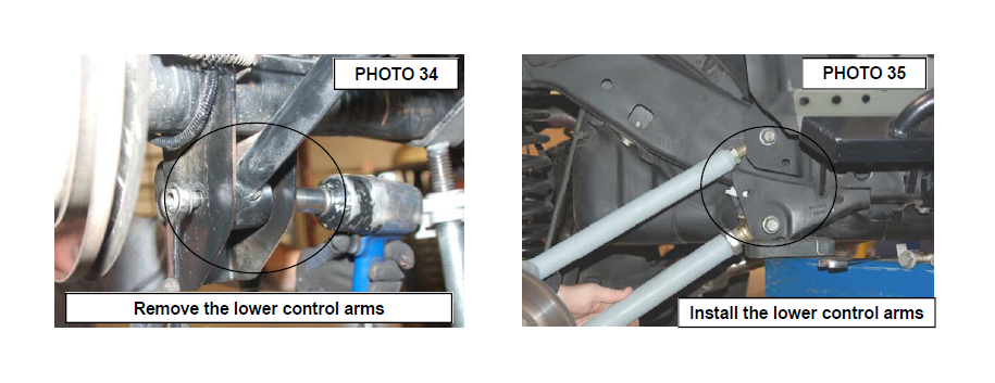
11. Using a 21mm socket remove the bolts securing the lower control arms at both the axle and frame. Passenger side lower shown in Photo 34. Remove the control arms and retain the hardware for reuse.
12. Assemble the bushings/sleeves and heim joints in the new lower control arms and adjust them to a length of 20 1/2” from center of hole to center of hole and tighten the jam nut using a 1 7/8” wrench. Install the hiem on the frame and the opposite end on the axle with the factory hardware using a 21mm wrench. See Photo 35. Do not fully tighten at this time.
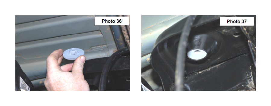
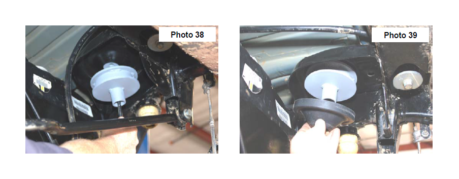
13. Install the new coil spring spacer with supplied washer/nut retainer and secure the assembly with supplied 1/2” x 2 3/4” bolt & lock washers through the factory coil mount as shown in Photo 36,37 & 38.
14. Install the factory coil spring isolator as shown. See Photo 39.
15. Install the top of the coil back onto the coil seat. When installing the bottom of the coil into the seat rotate the coil until the pigtail hits the spring stop. Lower vehicle slightly, watching coils to assure they properly seat on top
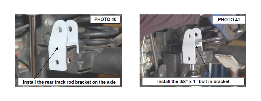
16. Position the rear track bar bracket over the rear factory track bar mount. See PHOTO 40 . Verify that the original track bar mounting hole and the hole in the new track bar bracket are aligned vertically. Using the track bar bracket as a template mark and drill a 13/32” hole in the top of the original track bar mount from the top.
17. Insert the supplied sleeve, inside the factory track bar mount. Insert the supplied 14mm x 80mm bolt through the bracket, factory mount, and sleeve secure using the supplied nut. Tighten using a 22mm wrench.
18. Install using the .375-16 x 1” bolt, washer through the drilled hole from the top and secure with flange nut using a 9/16” wrench and socket. See PHOTO 41.
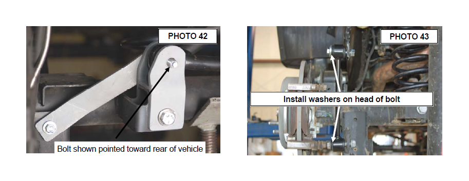
19. Install strap as shown in PHOTO 42. The bracket / factory track bar will install in place with the supplied 14mm x 80mm bolt & nut (upper hole) with the head of the bolt on the front by the coil spring. Install the supplied 3/8” x 1 1/4” top lock nut /washer on the shock mount and brace. The passenger side mount on the track bar will be installed in a later step. Tighten the hardware using a 9/16” and 22mm wrench / socket.
20. Locate the 4 sway bar link sleeves. Insert the supplied 1/2” inner diameter sleeves into the sway bar link bushings. Using the supplied .500-16 x 2.75” bolts, washers and nuts from 1681bag, install the sway bar links to the sway bar, and axle mount., and tighten using a 13/16” socket and 7/8” wrench. See PHOTO 43. Make sure the bolts are installed with the head of the bolt toward the tire as shown.
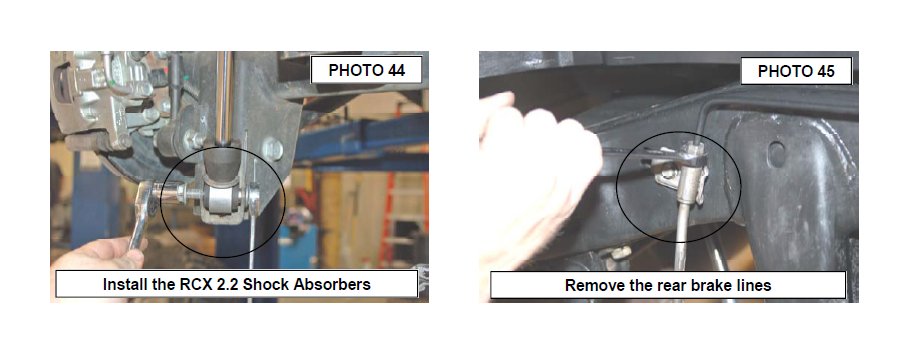
21. Install the supplied bushings and sleeves from 1681Shock bag2 to part # 660586 rear shocks. Install the RCX 2.2 series shocks using the factory hardware, using a 18mm socket for the top, and a 18mm socket for the bottom. Shaft end of the shock will be pointed down. The shocks have a built in bump stop. A longer bump stop will not be needed. See PHOTO 44.
22. Remove the rubber brake line from the steel line using a 12mm wrench as shown in Photo 45 and remove the brake line from the caliper using a 15mm wrench.
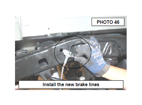
23. Install the new brake line bracket using a 10mm wrench and stock hardware to secure to factory location. Install the new brake line on the hard line and tighten. Install spring clip as shown in Photo 46. Install on the caliper with supplied
crush washers, using a 15mm wrench.
24. Reinstall the rear tires/wheels, using a 19mm deep well socket
25. Lower the vehicle to the floor.
26. Using a 21mm socket tighten the front and rear lower control arms, both ends to 130 ft.lbs.
27. Using a 18mm socket tighten the front upper control arms, both ends to 80 ft.lbs
28. Using a 21mm socket tighten the rear upper control arms to 130 ft. lbs.
29. Make sure the body is centered over the rear axle and install the rear track rod bracket in the factory location on the frame with the factory hardware and using a 21mm wrench.
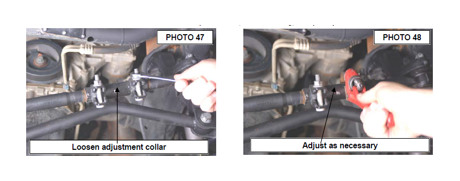
30. Adjust front draglink to center the steering wheel before driving by loosening the two bolts and turning the adjustment collar. See PHOTO 47 & 48.
IMPORTANT NOTE : The draglink must be adjusted to the center steering wheel BEFORE the vehicle is driven. Failure to do so will cause a computer error, odd handling, and poor performance.
POST INSTALLATION
1. Confirm that the draglink was adjusted to the center steering wheel BEFORE the vehicle is driven. Failure to do so will cause a computer error, odd handling, and poor performance.
2. Check all fasteners for proper torque. Check to ensure there is adequate clearance between all rotating, mobile, fixed and heated members. Check steering for interference and proper working order. Test brake system.
3. Perform steering sweep. The distance between the tire sidewall and the brake hose must be checked closely. Cycle the steering from full turn to full turn to check for clearance. Failure to perform inspections may result in component failure.
4. Re-torque all fasteners after 500 miles and recheck after 1000 miles. Alignment must be checked by a qualified mechanic. Visually inspect components and re-torque fasteners during routine vehicle service.
5. Readjust headlights to proper settings.
6. Have a qualified alignment center realign the front end, to the factory specifications immediately.
Caster preferred 4.6 degree range ,- 1 degree
Camber preferred –0.25 degree range ,- 0.63 degree
Toe-in preferred 0.15degree range ,- 0.15 degree
MAINTENANCE INFORMATION
It is the ultimate buyers responsibility to have all bolts/nuts checked for tightness after the first 500 miles and then every 1000 miles. Wheel alignment steering system, suspension and driveline systems must be inspected by a qualified professional
mechanic at least every 3000 miles.