 FREE 1 to 3-Day Delivery on Orders $149+ Details

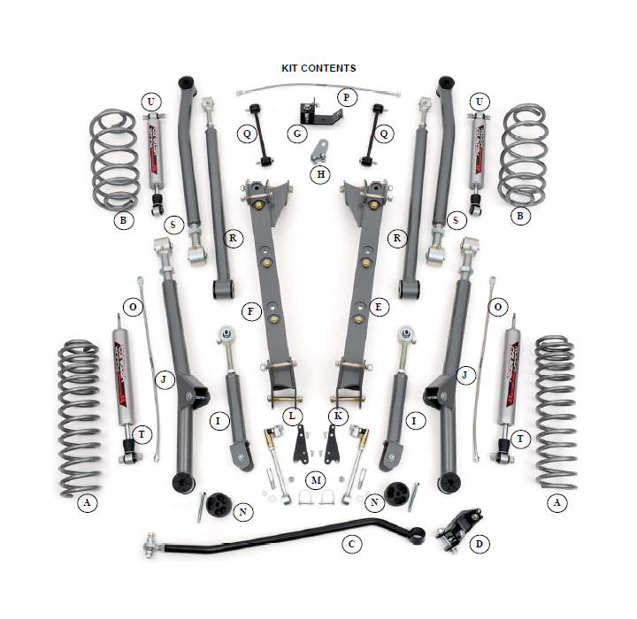
How to Install Rough Country 4" X-Series Long Arm Lift Kit on your 1997-2006 Wrangler
Tools Required
- Spring Compressor
- Silicone spray
- Drill assortment
- Hammer
- Combination wrenches
- Torx key socket
- File
- Floor jacks
- Wheel chocks
- 1/2" drill motor
- 11/32" Drill bit
- 13/32" Drill bit
- 17/32" Drill bit
- 19/64" Drill bit
- Torque wrench
- 1/2 drive ratchet and sockets
- Al

Shop Parts in this Guide
PRODUCT USE INFORMATION
As a general rule, the taller a vehicle is the easier it will roll. We strongly recommend seat belts and shoulder harnesses should be worn at all times. Avoid situations where a side rollover may occur.
Braking performance and capabilities are decreased when significantly larger/heaver tires and wheels are used. Take this into consideration while driving. Also, speedometer recalibration is necessary when larger tires are installed.
Do not add, alter, or fabricate any factory or after-market parts which increase vehicle height over the intended height of the Rough Country product purchased. Mixing component brands, lifts, voids all warranties. Rough Country makes no claims regarding lifting devices and excludes any and all implied claims. We will not be responsible for any product that is altered.
Post suspension system vehicles may experience drive line vibrations. Angles may require tuning and U-joints may need to be replaced
The 2 1/2” long arm suspension system was developed for 33x12.50x15 tire on an after market 8” wide wheel with 3.75” of back spacing. A 35x12.50x15 tire on an after market 8” wide wheel with 3.75” of back spacing can be used, but only if high fender clearance kits are installed.
Due to the inconsistency of vehicles when manufactured and the various options available, the amount of actual lift gained by this lift kit will vary. On models outfitted with extra bolt-on equipment and accessories, Rough Country offers new coil spring isolator pads made from polyurethane to boost ride height 3/4". These are available for the front or rear.
• With the installation of this kit and larger tires it is highly recommended that an aftermarket stabilizer(s) be added.
• Additionally, the exhaust system must be modified by an exhaust specialist to clear all components.
• On Rubicon models the air compressor for the air lockers on the frame by the rear of the skid plate will have to be relocated. Refer to installation instructions for detail.
NOTICE TO DEALER AND VECHICLE OWNER
Any vehicle equipped with any Rough country product must have the “Warning to Driver” decal installed on the sun visor or dash. The decal is to act as a constant reminder for whoever is operating the vehicle of its unique handling characteristics. INSTALLING DEALER—It is your responsibility to install the warning decal and to forward these installation instructions on to the vehicle owner for review and to be kept in the vehicle for its service life.
We hope installing your Rough Country lift kit is a positive experience. Please note that variations in construction and assembly in the vehicle manufacturing process will virtually ensure that some parts may seem difficult to install. The use of pry bars and tapered punches for alignment is considered normal and usually does not indicate a faulty product. However, if you are uncertain about some aspect of the installation process, please feel free to call our tech support department at 800-222-7023. We do not recommend that you modify the Rough Country parts in any way as this will void any warranty expressed or implied.
IMPORTANT PRE—INSTALLATION INSTRUCTIONS
Prior to beginning this installation it is always good to use a penetrating oil and spray all fasteners that will be removed. Typically the transfer case bolts are difficult to remove without having done this step.
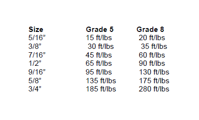
TORQUE SPECS:
Listed below are generic torque specs that are to be used when no specific spec is listed in the instructions. Please note it is extremely important to tighten all fasteners to the proper specs.
FRONT INSTALLATION
1. Place the vehicle on a level surface. Using a floor jack place the vehicle on jack stands front and rear to install the long arm kit. The jack stands will need to be placed near the front and rear of the vehicle to allow access to install the long arm components.
2. Remove the front and rear tires and wheels.
3. From inside the engine compartment, remove the upper stud nut, retainer and grommet from both of the front shocks using a 15mm socket.
4. Remove both of the front sway bar end links using a 15mm wrench for the upper and a 18mm wrench for the lower. Retain lower link hardware for re-use.
5. Place a floor jack underneath the axle for support and complete the removal of the front shock absorbers from the lower mount using a 13mm Socket. Retain the stock lower hardware for reuse.
6. Do not reuse the original factory shocks.
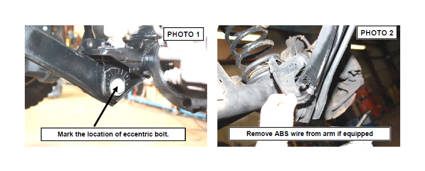
7. If your axle is equipped, mark the position of the lower control arm cam bolt and axle brackets for installation reference. See Photo 1. If equipped with ABS brakes, remove the sensor wires and clamps for the inside of the lower arms and save clamps for re-use. See Photo 2.
8. Remove the track rod from the axle and from the frame using a 15mm (axle) & 18mm wrench (frame). Retain the axle hardware for reuse.
9. Remove the coil spring clip located on the bottom coil seat on the driver side of the vehicle using a 13mm socket. Retain the clip and hardware for reuse.
10.Remove the brake caliper from the axle using a 13mm socket and secure out of harms way.
11.Lower the axle and remove the coil spring. A coil spring or strut compressor may be needed to remove the stock coil spring.
12.Support the front axle and remove the stock lower control arm by removing the nut, cam, and cam bolt (if equipped) from the axle bracket and then removing the nut and bolt from the frame bracket doing one side at a time using a 21mm socket & wrench. Retain the stock hardware.
13.Remove the upper arm from the mount using a 15mm wrench. Do not retain stock hardware.
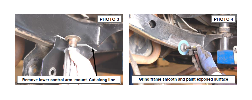
14.Cut the stock lower control arm mounts from the frame as shown in Photo 3 by cutting the weld that secures the bracket to the frame using a cutting wheel or similar cutting tool. Take care not to cut in to the frame rail.
15.After the bracket is removed, grind the surface smooth as shown in Photo 4 and paint the area to prevent rusting.
16. On the rear, remove the stock shocks and rear sway bar links using a 13mm socket on the upper and 18mm socket / wrench on the lower shock mount. Use a 15mm on the sway bar links. Retain hardware for reuse.
17. Support the rear axle with a floor jack and remove the rear track rod from the axle using a T55 Torx bit and a 15mm & 18mm wrench on the frame. Retain the hardware for reuse.
18. Lower the axle and remove the coil springs. Remove the rear sway bar links using a 15mm socket / wrench. Retain the upper hardware for reuse
19. Support the rear axle. Remove the brake line from the upper control arms using a 13mm wrench. Remove the lower control arms using a 21mm wrench & socket. Retain the factory axle hardware.
20. Remove the upper control arms from the rear axle using a 15mm socket / wrench. Retain axle hardware for reuse.
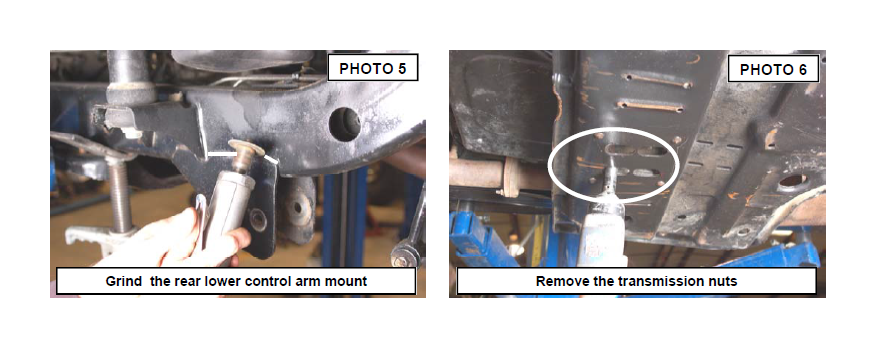
21. Cut the stock rear lower control arm mounts from the frame as shown in Photo 5 by cutting the welds that secures the bracket to the frame using a cutting wheel or similar cutting tool. Take care not to cut in to the frame rail. Paint the exposed surface to prevent rusting.
22. Remove the transmission nuts as shown in Photo 6 with a 13mm socket to allow the skid plate to be removed. Retain the factory hardware. On Rubicon models, remove the compressor bracket from the skid plate using a 13mm wrench. Retain the hardware for reuse. Removal of the compressor from the vehicle is recommended to ease in installation.
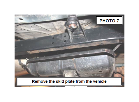
23. Support the factory skid plate, and remove the 6 bolts (3 each side) that secure it to the frame using a 3/4” socket. Retain the factory hardware. See Photo 7. If equipped with a forward skid plate (present on most auto transmission models) remove at this time using a 13mm & 3/4” wrench. This skid plate will not be reused. Lower the main skid plate and remove for trimming. Make sure stock lines are not pulled or overextended.
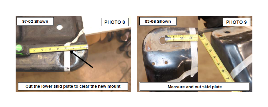
24. On 97-02 models , measure back 2 3/8” & over 5” over on the drivers side only rear corner of the skid plate and mark with tape. See Photo 8. Cut using a reciprocating saw. Grind the edges smooth. On 03-06 models measure back 2 3/4” from hole edge as shown on both sides of the skid plate and 6 1/2 from the sides and cut using a reciprocating saw. See Photo 9.
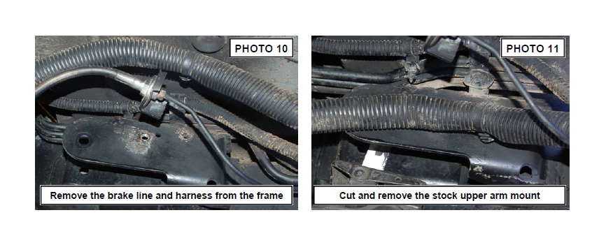
25. The rear stock upper control arm mounts will have to be removed to allow clearance for the rear long arms. Using a T30 Torx head bit remove the brake line bracket and wiring hardness from the stock mount on the drivers side. See Photo 10. Retain hardware for reuse. Driver side shown.
26. Using a reciprocating saw remove the upper mount as shown taking care to not damage the brake lines and gas lines. See Photo 11.
27. Remove the passenger side mount using a reciprocating saw.
28. After mount has been removed grind the area smooth and paint to prevent rust.
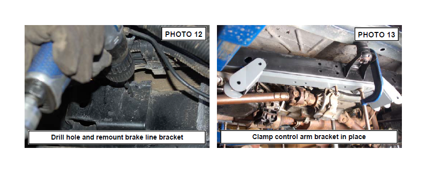
29. Using a 19/64” drill bit, drill hole as shown to reinstall the brake line bracket. See Photo 12. The brake line will be installed later.
30. Proceed to frame bracket install.
31. Align the holes in the frame with the new control arm bracket and install the factory skid plate bolts. Clamp in place using a large c-clamp. See Photo 13.
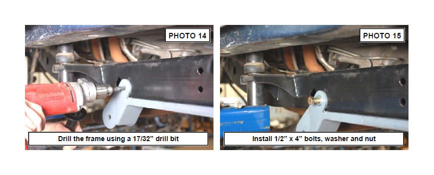
32. Using the new bracket as a guide, drill using a 17/32” drill bit through the inner and outer frame rail. See Photo 14. NOTE: The drill must be kept level for the frame holes to align with the new bracket. Note: Use caution when drilling the frame rail to avoid any lines on the inside of the frame rail, including fuel lines and brake lines.
33. Install the supplied 1/2” x 4” bolts, washers and nuts as shown in Photo 15 through the frame rail and tighten using a 3/4”wrench. Repeat steps 29-31 for the opposite side
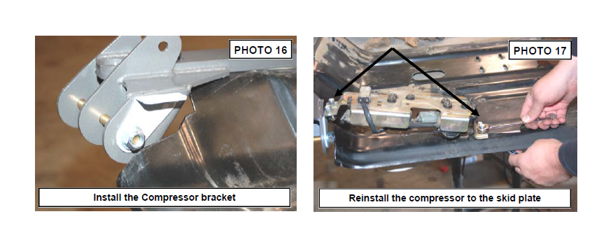
34. On Rubicon Models, the compressor bracket will be installed on the rear lower control arm bolt as shown in Photo 16. Temporarily insert 9/16” x 7” bolt at this time and continue to next step.
35. Using the stock compressor bracket as a guide, align the hole in the frame mount bracket and drill two holes using 11/32” drill bit and secure to the skid plate using the supplied 5/16” x 1” bolts, washer and nuts. The compressor will be secured to the new bracket with the supplied 5/16” x 1” bolts, washer and nuts. See Photo 17.
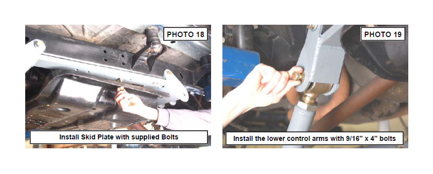
36. Reinstall the skid plate with the supplied 1/2” x 4 1/2” for 97-02 Models and 12mm x 65mm bolts & washers for 03 and up models. Tighten the 1/2” bolts using a 3/4” socket and the 12mm using a 19mm socket See Photo 18.
37. Locate the front lower control arm bushings and lubricate them with a lithium grease. Assemble the bushings and sleeves in the lower control arm. Adjust the arm to a length of 29 3/4” from center of bushing to center of bushing. Tighten jam nut using an adjustable wrench.
38. Install the new front lower control arm in the new mount with the supplied 9/16” x 4” bolts, washers / nuts making sure the joint is centered. Do not tighten at this time. See Photo 19.
39. Install the lower control arm on the axle with the factory hardware. See Photo 20. Do not tighten at this time.
40. Assemble the front upper control arm and adjust to a length of 13 1/2” from center of hole to center of bushing. Install on the new lower control arm with the supplied 10mm x 80mm bolt, washers / nuts. See Photo 21. Do not tighten at this time. Tighten jam nut using an adjustable wrench.
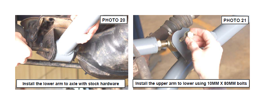
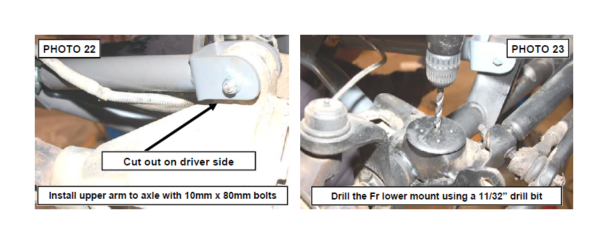
41. Install the new upper arm to the axle using the supplied 10mm x 80mm bolt, washers & nuts. Do not tighten at this time. See Photo 22. If installing on a vehicle equipped with a Dana 44 front axle, be sure to install the arm on the drivers side with the cut out over the differential to allow clearance. See Photo 22.
42. Drill the lower coil mount as shown in Photo 23 using a 11/32 drill bit.
43. Slide the bump stop extension in the new coil as shown in Photo 24 with the supplied 3/8” x 3 1/2” self taping bolt and install the coil spring in the factory location, making sure the coil is fully seated in the lower mount.
44. Tighten the bump stop extension bolt with a 9/16 wrench. Do not over torque the bolt. See Photo 25.
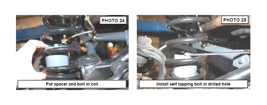
45.Remove the cotter pin and nut from the drag link at the pitman arm. Retain the nut to be reused. Separate the drag link ball stud from the pitman arm with a puller tool. Do not use a pickle fork.
46.Mark the position of the original pitman arm. Remove the nut and washer from the steering gear box and using a pitman arm puller, remove the pitman arm. Align and install new pitman arm on the steering gear shaft. Install the washer and nut. Tighten to 185 ft. lbs.
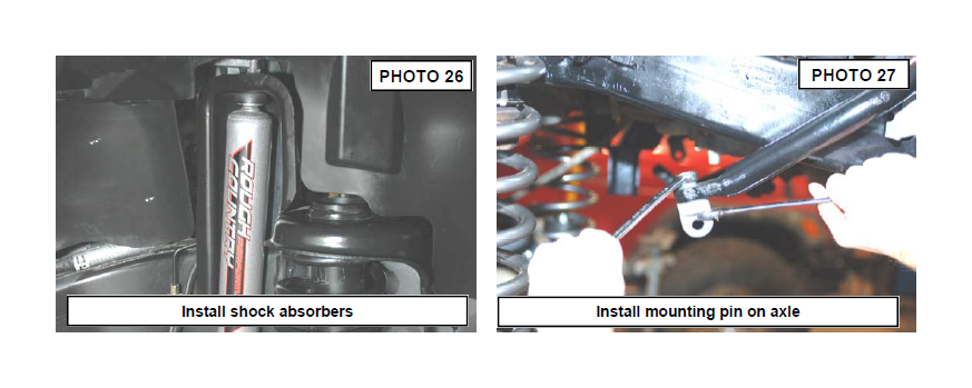
47.Locate the front 2.2 Series shock absorber and install in the factory lower mounts with the factory hardware— these shocks are designed to have piston mounted down. See Photo 26. Install the new upper stud bushings and tighten the upper mounting point using a 9/16” wrench, slightly bulging the bushing. Do not over tighten stud bushing.
Tighten the bar pin on the bottom of the shock with the stock hardware using a 12mm wrench.
48.Install the upper sway bar mount on the top of front sway bar where the stock link was secured, using the supplied 3/8” x 1.25” bolt, lock washer, and washer. Tighten using a 9/16” wrench making sure the mount is straight. Note that washer will conform to sway bar surface and be pulled in. See Photo 27.
49.Assemble the sway bar link with the link body, the jam nut and rod end Adjust the sway bar to a length of 11 1/4” from top to bottom. Tighten the jam nut against the rod end using a 19mm & 5/8” wrench.
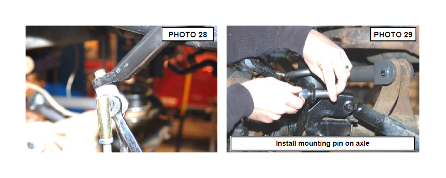
50.Install the link on the upper sway bar mount as shown in Photo 28. Tighten using a 5/8” & 18mm wrench.
51.Install the supplied pin on the axle as shown in Photo 29. Tighten using a 3/4” wrench.
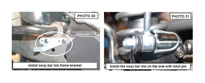
52.Remove the bolts securing the plastic shroud to the frame and install the driver and passenger side frame mount brackets in the holes shown for the disconnect kit using the factory holes and the supplied 1/4” x 3/4” bolts & washers. See Photo 30. Tighten using a 7/16” wrench, be careful to not over tighten. Please note there is a passenger
and driver side bracket.
53.Swing the sway bar link down and install on the lower axle mounting pin. Install the hitch pin. See Photo 31. It may be necessary to install the link on the axle after the vehicle is on the ground.
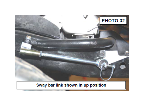
54.When disconnecting the sway bar, remove the sway bar link and place it on the frame mount as shown in Photo 32 to keep the sway bar link from interfering with front end components.
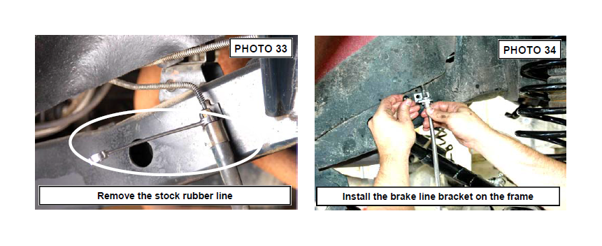
55.Remove the stock front brake line from the metal line at the frame rail using a 3/8” wrench. Remove the brake line from the caliper using a 14mm socket. Retain stock hardware to reinstall the brake line. A catch pan is recommended to avoid a fluid mess. See Photo 33.
56.Remove the stock line from the frame rail using a T30 Torx head bit. Retain the bolt for reuse.
57.Install the new brake line bracket on the frame rail as shown in See Photo 34 with the stock hardware using a T30 Torx head bit. Install the new Rough Country brake line on the stock metal line and install supplied brake line clip. Install on the caliper with stock caliper bolt and brake line washers using a 14mm socket. Install the caliper on
the axle and tighten using a 13mm socket.
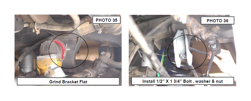
58.Grind the back side of the mount smooth to allow the track rod bracket to be installed. See Photo 35.
59. Install the new track rod bracket on the frame as shown in Photo 36 using the supplied 1/2” x 1 3/4” bolt, washer & nut in the stock mount. Tighten using a 19mm Socket & wrench. View from the passenger side.
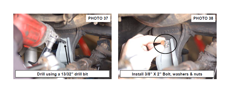
60. Using the bracket as a guide, drill the upper hole using a 13/32” drill bit. See Photo 37.
61. Install the supplied 3/8” x 2” bolt in the drilled hole with the washers & nut. Tighten using a 9/16” socket & wrench. See Photo 38.
62.Install the supplied bushings and sleeves in the track rod body and install the heim joint, spacers and jam nut. Adjust to a length of 31 3/4” from end to end for a starting point. The tack rod will be installed later.
63.Moving to the rear of the Jeep, Grease the supplied bushings with a lithium grease and install the bushings in the rear upper and lower control arms. TJ Jeeps: Adjust the lower control arms to 27 3/4” and the upper control arms to 29” long. LJ Jeeps: Adjust the lower control arms to 37 3/4” and the upper control arms to 39” long.
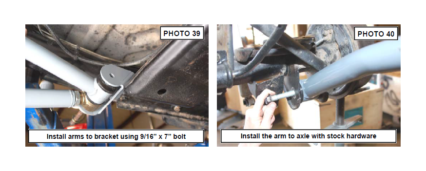
64.Install the new rear lower & upper control arm in the new mount with the supplied 9/16” x 7” bolts. Washers / nuts making sure the lower arm joint is centered in the mount. Do not tighten at this time. See Photo 39.
65.Install the new rear lower control arm on the rear axle with the factory hardware. See Photo 40. Do not tighten.
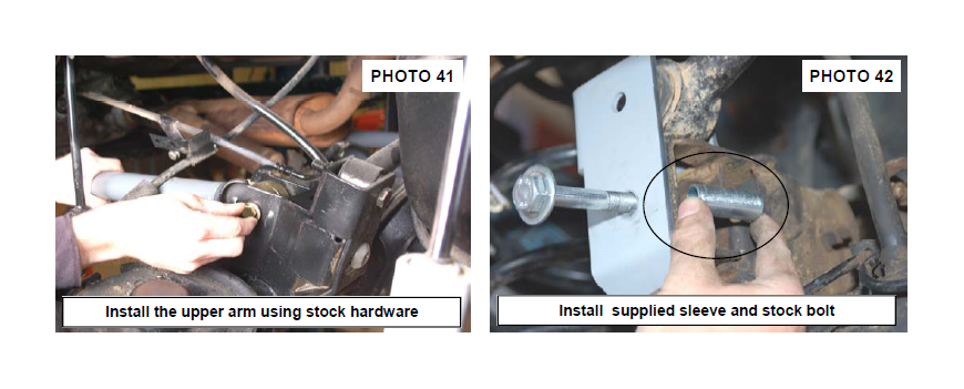
66.Install the upper arm on the axle using the stock hardware. Do not tighten at this time. See Photo 41.
67.Locate the new track rod bracket and install on the rear axle mount as shown in Photo 42 with the supplied crush sleeve using the stock bolt and flag nut. Tighten using a T55 torque head bit.
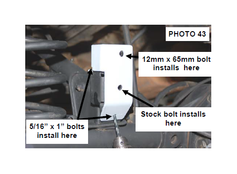
68.Using a drill enlarge the two factory holes in the factory mount using a 11/32” drill bit as shown and install the supplied 5/16” x 1” bolts, washers & nuts in the bracket as shown in Photo 43. Tighten using a 13mm wrench.
69.Install the track rod on the frame mount on the passenger side using the factory hardware. Do not tighten at this time. The track rod will be installed on the axle and
tightened on both ends after the vehicle has been lowered to the ground and is supporting it own weight. This is done to ensure the axle is centered under the body.
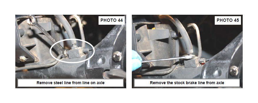
70. Separate the stock rubber line from the steel line at the axle using a 3/8” brake line wrench and remove the stock brake line from the axle using a 9/16” wrench. See Photo 44 & 45.
71. Separate the steel line from the rubber line on the driver side frame rail.
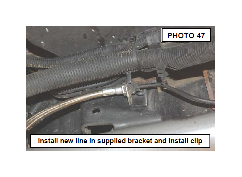
72. Install the supplied brake line bracket with the factory hardware on the frame in the hole drilled earlier in the install. Tighten using a T30 torx head bit. Install the brake line to the bracket on the frame and secure with the supplied clip. See Photo 47.
73. Install the brake line on the axle to the hard lines using a 3/8” brake line wench. Secure the new brake line to the axle with the stock hardware using a 9/16” wrench.
74. Install the new Rough Country coil springs making sure the rubber damper in positioned in the upper mount. It will be necessary to use a coil spring or strut compressor to install the new coil springs.
75. Install the rear Rough Country 2.2 Shock absorber on the upper mount with the factory hardware. Tighten bolts using a 15mm & 18mm wrench. (Stock shocks
shown in picture). RCX 2.2 Series shock absorbers are designed to be installed with the piston down and body up.
76. Install the wheels / tires and tighten the lug nuts to the factory specifications using crossing pattern.
77. Remove the jack stands and lower the vehicle to the ground.
78. On the front lower control arms; align the reference marks on the adjustment cams and lower arm axle brackets and tighten to 85 ft. lbs using a 21 socket & wrench. Tighten the upper using a 15mm socket & wrench. Repeat for the rear of the vehicle. Tighten front track rod in mounts using a 15mm socket / wrench.
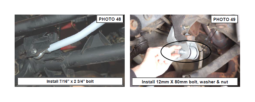
79.Install the track rod on the axle with the supplied 7/16” x 2 3/4”mm bolt, washer & nut. Do not tighten at this time. See Photo 48.
80.Swing up the track rod and adjust as necessary to center the vehicle over the axle and install in the new track rod bracket with the supplied 12mm X 80mm bolt and flange nut. Tighten to 55 ft/lbs using a 15mm wrench and snug the jam nut using a 1 1/2” wrench. See Photo 49. It is important to center the vehicle over the axle to ensure proper tracking and alignment.
81. Install the rear track rod on the axle and tighten with factory hardware
82. Assemble the new sway bar links with the supplied 10mm sleeves.
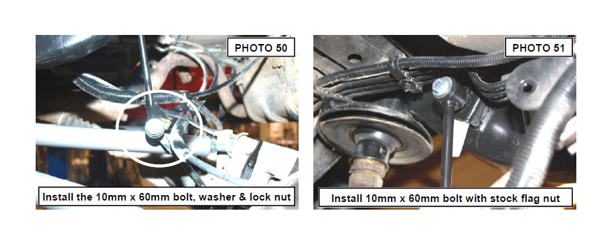
83. Install the new sway bar links on the sway bar with the supplied 10mm x 60mm bolts, washers and lock nuts. See Photo 50.
84. Install the sway bar link on the frame using the stock flag nuts and the supplied 10mm x 60mm bolts and washers. See Photo 51.
POST INSTALLATION
1. Rotate driveshaft and check for interference at differential yoke and u-joint. If necessary, lightly dress casting(s) and/or U-joint tabs in order to eliminate binding.
2. Bleed brake lines and test brakes before driving. Check for leaks.
3. Have a qualified alignment center realign front end to factory specs. As a general rule you set caster to the minimum of the factory spec and set toe-in to the maximum.
4. Install Warning to Driver decal on sun visor.
5. Adjust headlights to proper settings
6. Grease all control arms and periodically grease as required.
7. All components must be retightened after 500 miles, and every three thousand miles after installation.
8. The factory exhaust must be modified / rerouted to have adequate clearance on all fixed and moving components.
TROUBLESHOOTING TIPS
Problem: Driveline Vibrations
Possible Solution: Check all u-joints to insure that there is no wear on the existing hardware caps. Even a new vehicle can cause vibrations in the angle on the U-joint is changed after being run for even a short period of time.
Possible Solution: The transfer case drop brackets must be installed with the 4” lift, if you do not plan to run a slip
yoke eliminator.
Problem: Your Jeep does not steer, or track correctly.
Possible Solution: The steering geometry is corrected when the pitman arm is installed. If the steering is short or offset after installing the lift with the pitman arm, the alignment shop should adjust the linkages on the front axle to line the steering geometry back.
Possible Solution: If you are experiencing bump steer or axle float after the alignment, you will need to check the track bar to ensure that the tie rod end is not worn or damaged. This will allow the axle to float from side to side.
Problem: You experience “High Speed Wobble” after hitting bump at 35-40mph. Possible Solution: “Death wobble” is usually a combination of items and typically there is not one easy fix. We recommend you follow these steps when trying to identify source. Start by looking for any loose movement in the steering. Watch the tie-rod ends where they connect to the steering knuckle arms. Watch the drag link and the ends. Watch the track bar—it should remain tight without side to side movement when dry turning. Make sure your tires are balanced—we recommend they be “road force” balanced. Lack of proper caster angles may be the problem. Last but not least is the steering stabilizer. A new stabilizer will not fix the problem, but a worn out one will make the situations worse.
