FREE 1 to 3-Day Delivery on Orders $149+ Details

How to Install Rough Country 3.5" Series II Lift Kit on your 2007-2013 Wrangler
Tools Required
- Jack
- Jack Stand
- 13/32" Drill Bit
- Drill
- Pitman arm puller
- WD-40
- 3/8" Drill Bit
- 21mm Socket
- 21mm Wrench
- 7/16" Wrench
- 9/16" Wrench
- 9/16" Socket
- Tools Needed:10mm Wrench
- 14mm Wrench
- 16mm Wrench
- 18mm Wrench
- 18mm Socket
- 19mm Wrench
- 19mm Deep Well Socket
- 7/8" Wr
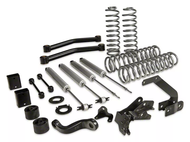
Shop Parts in this Guide
Thank you for choosing Rough Country for your suspension needs.
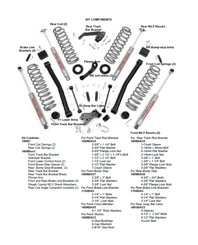
Please read instructions before beginning installation. Check the kit hardware against the parts list. Be sure you have all needed parts and know where they go. Also please review tools needed list and make sure you have needed tools.
PRODUCT USE INFORMATION
Rough Country Suspension products are intended to improve off road performance. Modifying your vehicle for off road use may result a vehicle in the vehicle handling differently than a factory equipped vehicle. Avoid situations where a side rollover may occur. Seat belts and shoulder harnesses should be worn at all times.
Do not add, alter, or fabricate any factory or after-market parts to increase vehicle height over the intended height of the Rough Country product purchased. Mixing component brands is not recommended.
This 3 1/2” suspension system was developed using a 35X12.50X17 tire with 4.5” to 4.75” of back spacing on aftermarket wheels. Stock wheels can be used with this kit with up to a 35x12.5 tire, but different tire manufactures designs may result in a tire width that could result in contact with the lower control arm and/or front sway bar link in a sharp turn. Please consult with your tire and wheel expert before purchasing. Stock Wheels can be used with the addition of a 1 1/2” wheel spacer. If questions exist we will be happy to answer any questions concerning the design, function, and correct use of our products by calling 1-800-222-7023.
IMPORTANT NOTES: Upon completing the install of this kit the draglink must be adjusted to center the steering wheel BEFORE the vehicle is driven. Failure to do so will cause the Vehicle Stability Program to not function properly , odd vehicle handling, and poor performance.
On Automatic equipped vehicles; due to use of an oversize driveshaft from the factory and inadequate factory clearance it may be possible for the front driveshaft to come in contact with the automatic transmission pan tearing the factory boot and rubbing on the shaft. Generally this occurs during heavy articulation when front sway bar links are disconnected and longer shocks are installed. If this is found to occur, the proper procedure would be to replace the oversize factory shaft with an aftermarket smaller diameter shaft to increase clearance between the transmission and front driveshaft. Rough Country does offer this driveshaft if needed.
NOTICE TO DEALER AND VEHICLE OWNER
Any vehicle equipped with any Rough Country product should have a “Warning to Driver” decal installed on the inside of the windshield or on the vehicle’s dash. The decal should act as a constant reminder for whoever is operating the vehicle of its unique handling characteristics.
FRONT INSTALLATION INSTRUCTIONS
1. Prior to installing this kit, with the vehicle on the ground, measure the heights of your vehicle. This measurement can be recorded from the center of the wheel straight up to the top of the inner fender lip. Record the measurements.
LF:__________ ,RF:___________,
LR:__________, RR:___________
2. Place vehicle in park and chock the rear wheels. Raise the front of the vehicle with a jack and secure a jack stand beneath each frame rail behind the front control arms. Ease the frame down onto the stands.
3. Remove the front tires/wheels, using a 19mm deep well socket.
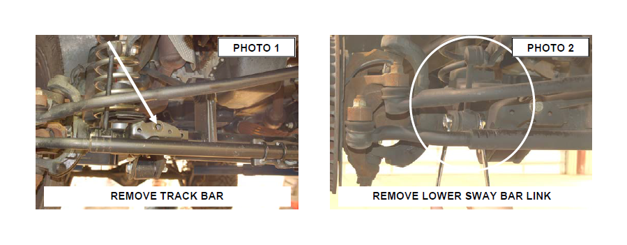
4. Using a 21mm socket, remove bolt securing the front track bar to the axle. Retain stock hardware. See Photo 1.
5. Using a 18mm socket and wrench remove the bottom sway bar bolts. See Photo 2.
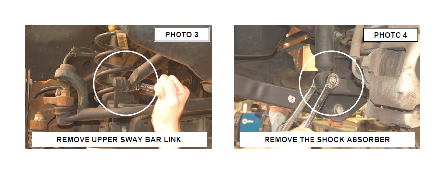
6. Using a 19mm socket and 18mm wrench, remove the top of the sway bar link. Retain hardware for later use. See Photo 3.
7. Remove the lower shock bolt using a 18mm socket and wrench as shown in Photo 4. Using a 16mm wrench unbolt the top of the shock and remove. Retain stock hardware.
8. On some models it will be necessary to remove the brake line bracket from the frame to allow the coils to be removed. Using a 10MM socket, remove the brake line bracket from the stock location. Note: The ABS wire may have to be unclipped from the brake line to allow the axle to be lowered to remove the coil springs.
9. Push down on the axle to allow room for the coils to be removed. Remove stock coil springs. Retain stock coil isolators.
10. With the axle supported, using a 21mm socket and wrench remove the lower control arm bolts at the axle and frame. Retain the stock hardware for reuse.
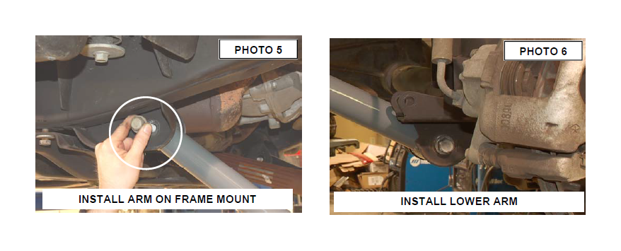
11. Install the new control arms in the upper mount as shown in Photo 5 with the stock hardware.
12. Install the arm on the axle with the stock hardware. Snug, but do not tighten hardware at this time. See Photo 6.
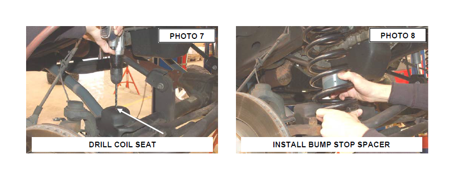
13. Place the supplied 2” bump stop in place on the lower coil seat. Mark & drill using a 3/8” drill bit. See Photo 7.
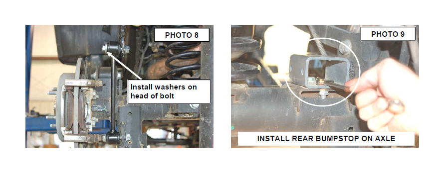
14. Be sure the factory rubber isolators are in place and install the front coil springs with the 2” bump stop pucks as shown in Photo 8. Insert the coil into the upper tower first, followed by the lower seat. Be sure that the coils are rotated so that they seat properly. Raise the axle enough to hold the coil springs in place.
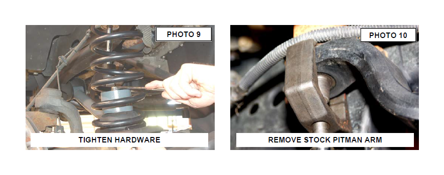
15. Secure the bump stop to the drilled hole in the lower seat using the supplied 3/8” x 3” bolts, washers and nuts.Tighten using a 9/16” wrench. See Photo 9.
16. Using a 21mm socket remove the tie rod end from the pitman arm. Remove the pitman arm nut using a 33mm socket.
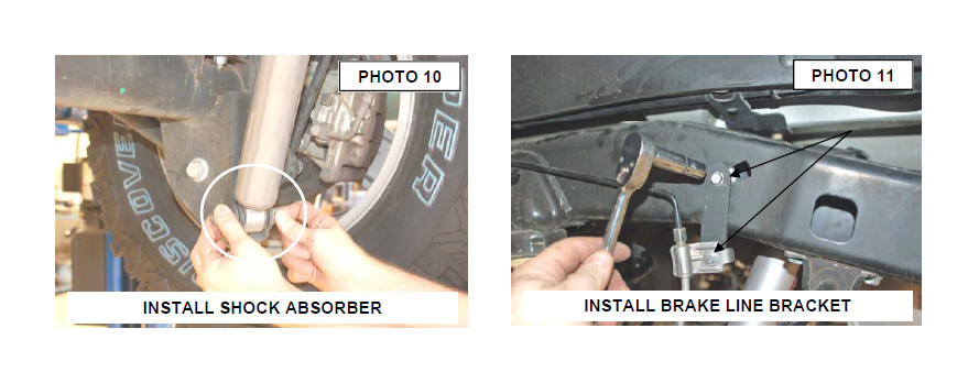
17. A pitman arm puller will be needed to remove factory pitman arm. See Photo 10.
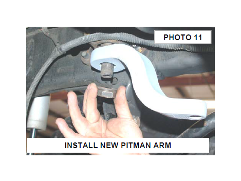
18. Lightly lube pitman arm splines with WD-40 and install the new pitman arm with the stock hardware. Tighten using a 33mm socket. See Photo 11. Reinstall the drag link on the new pitman arm with the stock nut and using a 21mm wrench. It might be necessary to use a 1/4” allen wrench to hold stud and tighten.
19. Install the bushings and sleeves from 1681bag2 into part # 658686 front shock. Position the cup washer and stem bushing on the stem end of the shock and insert the stem in the upper shock tower. Install the remaining bushing and washer and loosely secure using the supplied nut. Tighten using a 9/16” wrench until the bushing swells slightly.
20. Attach the lower end of the shock to the axle and secure using the stock hardware. Tighten to 80 ft/lbs.
21. Remove the stock stabilizer from the axle and tie rod mount using a 18mm wrench See Photo 12.
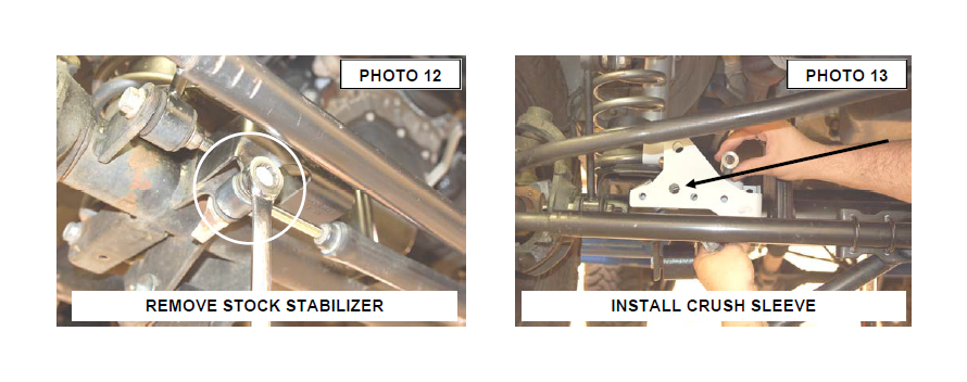
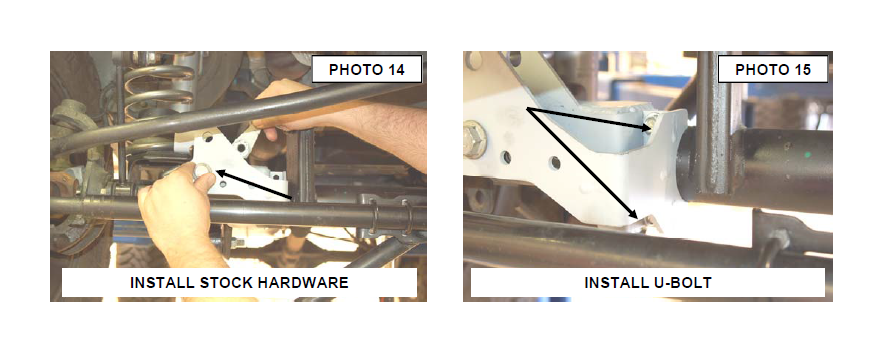
22. Install the track rod bracket as shown on the stock mount. Install the crush sleeve with the stock hardware as shown in Photo 13 & 14.Do not tighten at this time.
23. Install the supplied u-bolt and nuts in the bracket as shown in Photo 15. Do not tighten at this time.
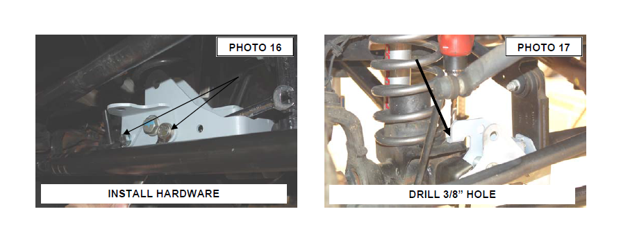
24. Install the two 3/8” x 1 1/4” bolts, washer and nuts in the new bracket and supplied stabilizer bracket if reusing the stock stabilizer in the far left holes as shown. If not installing the stock stabilizer, the two 3/8” x 1 1/4” bolts will be installed in the two far left holes in the bracket with out the supplied stabilizer bracket. See Photo 16.
25. Drill the rear mount using a 3/8” drill bit and install the 3/8” x 1 1/4” bolt, washer and flange lock nut. See Photo 17.
26. Tighten all 3/8” hardware using a 9/16” wrench.
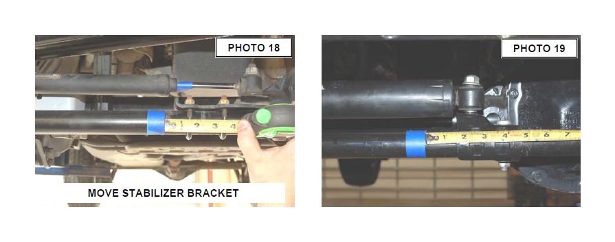
27. This next two steps will be performed if the stock stabilizer is retained. On 07-10 Models mark the location on the factory tie rod bracket on the tie rod and loosen the u-bolt nuts using a 13mm wrench. Slide the bracket down 1 1/4” rotate to position the stud up as shown and retighten tie rod end bracket. See Photo 18.
28. On 2011 models loosen the tie rod bracket using a 15mm wrench. Mark original location and move the bracket 1 1/2” and rotate the tie rod bracket as shown to allow full stroke of the stabilizer cylinder. See Photo 19.
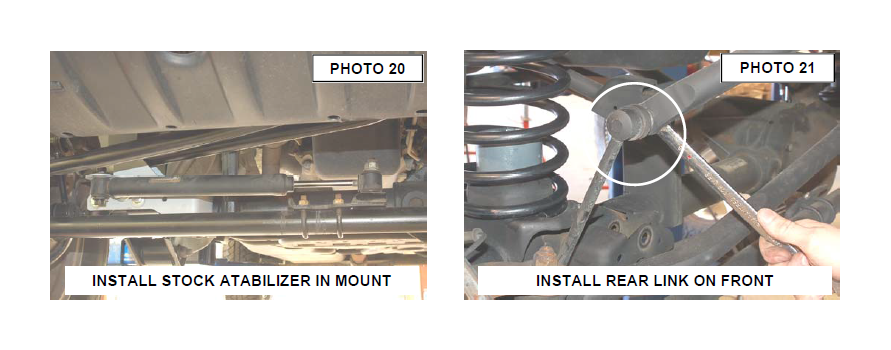
29. Install the factory stabilizer in the new track rod / stabilizer mount with the body of the stabilizer on the axle mount with stock hardware and tighten using a 18mm socket / wrench. See Photo 20.
30. Install the stock track bar into the new track rod bracket using the supplied 1/2” x 2 1/2” stock bolt/nut. Tighten using a 21mm & 22 mm socket / wrench.
31. On the rear of the vehicle remove the factory sway bar link using a 18mm socket and wrench on the lower. Remove the upper hardware using a 18mm wrench and a 19mm wrench on the ball joint end.
32. Install the factory rear sway bar link in place of the factory front sway bar link. Attach the swivel end of the link to the factory sway bar using the stock hardware. Line up the eye end of the link to the factory mount on the axle, attach using the factory hardware. Tighten the upper using a 18mm and 19mm wrench, and lower using a 18mm socket and wrench. See Photo 21.
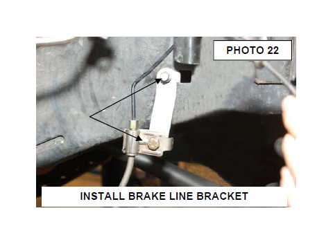
33. Locate the brake line bracket and install using the stock hardware. Install the stock brake line on the other end of the bracket using the supplied 1/4” X 1” bolts. See Photo 22. Use caution when moving the brake line to not kink the metal line.
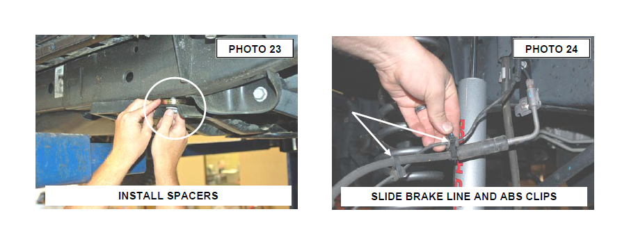
34. This step will be performed on vehicles equipped with the optional front transmission skid plate only. One side at a time, using a 18mm socket remove the bolt that holds the cross member to the frame in front of the rear upper control arm. Insert 2 washers to each side supplied in 1681bag, between the frame and cross member as shown in Photo 23. This will space the cross member down enough to allow driveshaft clearance at full flex. Tighten using the stock bolt. Repeat on opposite side.
35. Reinstall the front tires/wheels using a 19mm deep well socket.
36. If removed, relocate the plastic clips on the brake line to hold ABS Line. See Photo 24.
37. Lower the vehicle to the floor. 38. Proceed to rear installation.
REAR INSTALLATION INSTRUCTIONS
1. Jack up the rear of the vehicle and support the vehicle with jack stands, so that the rear wheels are off the ground. Chock front wheels. Position a jack so it supports, but does not raise the rear axle.
2. Remove the rear tires/wheels, using a 19mm deep well socket.
3. Using a 21mm socket remove the track bar bolt at the axle and secure the track bar out of the way.
4. Using a 21mm socket loosen, but do not remove the bolts securing the lower control arms at both the axle and frame.
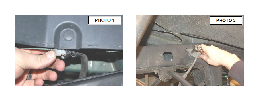
5. Using a 10mm wrench, unbolt the brake hose bracket at the frame. Retain hardware for later use. See Photo 1.
6. Remove and discard the rear shocks using a 18mm wrench on the lower mount and 15mm on the upper. Retain stock hardware.
7. Remove the diff vent hose from the inner fender on the passenger side. The hose will be relocated after installation. See Photo 2.
8. Lower the axle enough to remove the stock coil springs.
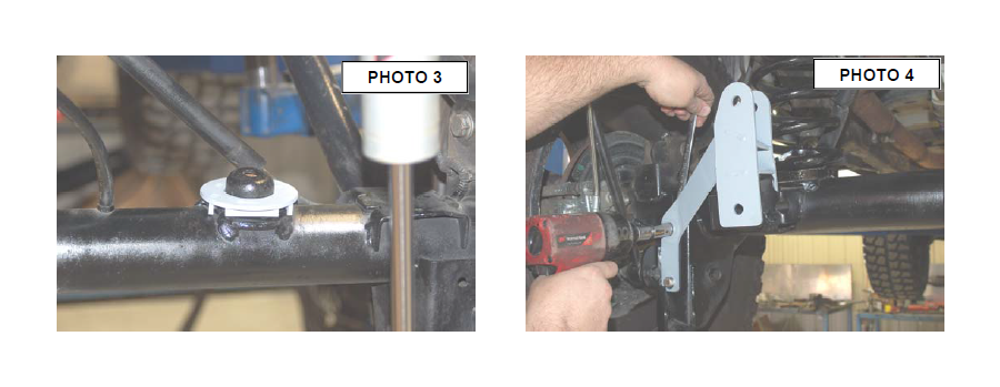
9. Install the rear coil correction spacer as shown in Photo 3.
10. Install the supplied rear coil springs. Rotate the coils so that they seat properly in the coil seat, raise the axle enough to seat the coil spring.
11. Place the bracket on the factory mount and install the supplied 3/8” x 1” Bolts , washers and Flange lock nuts as shown in the factory holes. Do not tighten at this time. See Photo 4.
12. Using the track bar bracket as a template mark and drill a 13/32” hole in the top of the original track bar mount.
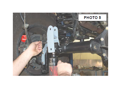
13. Install using the .375-16 x 1.25” bolt, washer through the drilled hole from the top and secure with flange nut using a 9/16” wrench and socket. See PHOTO 5.
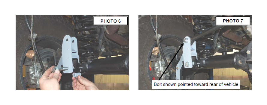
14. Insert the supplied sleeve, inside the factory track bar mount. Insert the supplied 14mm” x 80mm” bolt through the bracket, factory mount, and sleeve secure using the washer and nut. Do fully tighten. See Photo 6.
15. Tighten all track rod bracket hardware.
16. Install the factory track bar with the supplied 14mm x 75mm bolt washer & flange nut (upper hole) with the head of the bolt on the front by the coil spring. See Photo 7. The passenger side mount on the track bar will be installed in a later step.
17. Locate the 4 sway bar link sleeves. Insert the sleeves into the sway bar link bushings. Using the supplied .500-16 x 2.75” bolts, washers and nuts from 1681bag, install the sway bar links to the sway bar, and axle mount., and tighten using a 13/16” socket and 7/8” wrench. See Photo 8. Make sure the bolts are installed with the head of the bolt toward the tire as shown.
18. Install the bump stop spacers as shown on axle and secure with the supplied 3/8” x 3/4’ bolts, washers and nuts. See Photo 9.
19. Install the supplied bushings and sleeves to part # 658687 rear shocks. Install the using the factory hardware, using a 18mm socket for the top, and a 18mm socket for the bottom. See Photo 10.
20. Attach the brake line bracket to the location on the frame where the factory bracket was attached. Tighten using a 10mm wrench and stock hardware. Secure the factory bracket to the bottom hole of the relocation bracket using a 7/16 wrench and the supplied .250-20 x 1” bolts, washers, and nuts. See Photo 11.
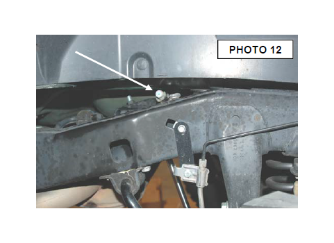
21. Slide the metal mount to the end of the line and reinstall the diff vent hose on the frame as shown in Photo 12.
22. Reinstall the rear tires/wheels, using a 19mm deep well socket
23. Lower the vehicle to the floor.
24. Using a 21mm socket tighten the front and rear lower control arms, both ends to 130 ft.lbs.
25. Using a 18mm socket tighten the front upper control arms, both ends to 80 ft.lbs
26. Using a 21mm socket tighten the rear upper control arms to 130 ft. lbs.
27. Make sure the body is centered over the rear axle and install the rear track rod bracket in the factory location on the frame with the factory hardware and using a 21mm wrench.
28. Adjust front draglink to center the steering wheel before driving by loosening the two bolts and turning the adjustment collar. See Photo 13 & 14.
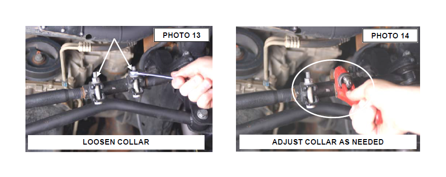
IMPORTANT NOTE : Upon completing the install of this kit the draglink must be adjusted to center the steering wheel BEFORE the vehicle is driven. Failure to do so will cause the Vehicle Stability Program to not function properly , odd vehicle handling, and poor performance.
POST INSTALLATION
1. Perform steering sweep. The distance between the tire sidewall and the brake hose must be checked closely. Cycle the steering from full turn to full turn to check for clearance. Failure to perform inspections may result in component failure.
2. Re-torque all fasteners after 500 miles and recheck after 1000 miles. Alignment must be checked by a qualified mechanic. Visually inspect components and re-torque fasteners during routine vehicle service.
3. Readjust headlights to proper settings.
4. Have a qualified alignment center realign the front end, to the factory specifications immediately.