 FREE 1 to 3-Day Delivery on Orders $149+ Details

How to Install Rough Country 3.25" Lift Kit w/shocks on your 1997-2006 Wrangler
Tools Required
- Spring Compressor
- Silicone spray
- T-55 Torx Head Bit
- Floor jacks
- Wheel chocks
- Drill Motor
- 5/16" Drill Bit
- 7/16" Drill Bit
- Torque wrench
- T-55 Torx Head Bit
- 1/2" Socket / Wrench
- 9/16" Socket / Wrench
- 3/4" Socket / Wrench
- 13mm Socket /Wrench
- 15mm Socket / Wre

Shop Parts in this Guide
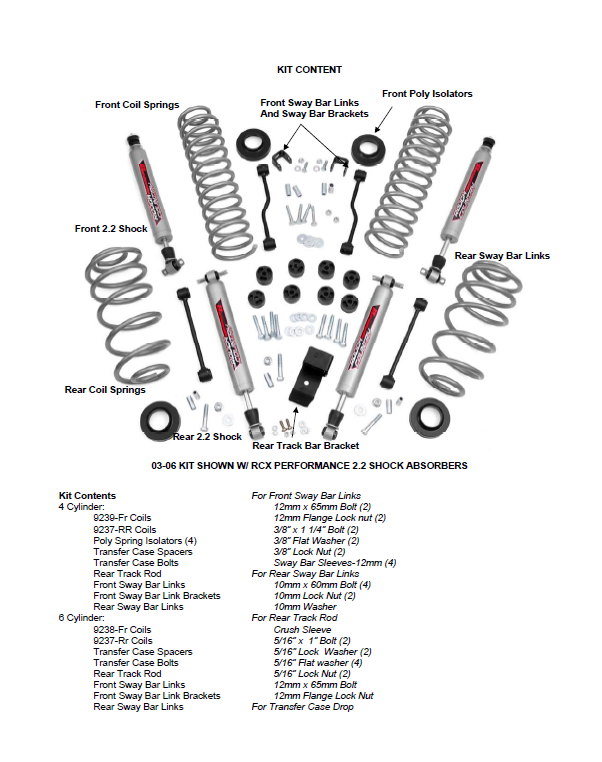
- Rough Country Suspension 3.25-Inch Suspension Lift Kit with Shocks (03-06 2.4L Jeep Wrangler TJ)
- Rough Country Suspension 3.25-Inch Suspension Lift Kit with Shocks (97-02 2.5L Jeep Wrangler TJ)
- Rough Country Suspension 3.25-Inch Suspension Lift Kit with Premium N2.0 Shocks (97-02 4.0L Jeep Wrangler TJ)
- Rough Country Suspension 3.25-Inch Suspension Lift Kit with Shocks (03-06 4.0L Jeep Wrangler TJ)
Thank you for choosing Rough Country for your suspension needs.
Rough Country recommends a certified technician installs this system. In addition to these instructions, professional knowledge of disassemble/reassembly procedures as well as post installation checks must be known. Attempts to install this system without this knowledge and expertise may jeopardize the integrity and/or operating safety of the vehicle. Please read all the instructions before beginning the installation. Check the kit hardware against the parts list. Be sure you have all the needed parts and understand where they go. Also please review the tools needed list and make sure you have needed tools.
PRODUCT USE INFORMATION
As a general rule, the taller a vehicle is the easier it will roll. We strongly recommend, because of rollover possibility, that the vehicle be equipped with a functional roll-bar and cage system. Seat belts and shoulder harnesses should be worn at all times. Avoid situations where a side rollover may occur.
Braking performance and capabilities are decreased when significantly larger/heaver tires and wheels are used. Take this into consideration while driving. Also, speedometer recalibration is necessary when larger tires are installed.
Do not add, alter, or fabricate any factory or after-market parts which increase vehicle height over the intended height of the Rough Country product purchased. Mixing component brands, lifts, and/or combining body lift with suspension lifts voids all warranties. Rough Country makes no claims regarding lifting devices and excludes any and all implied claims. We will not be responsible for any product that is altered.
This 3 1/4” suspension system was developed for 33 x 12.5 tire on an after market 15x 8” wide wheel with 3.75” of back spacing. The use of stock wheels with larger than stock tires may cause the tire to come in contact with the lower control arm at full turn. The use of aftermarket wheels is recommended to avoid this. Due to the inconsistency of vehicles when manufactured and the various options available, the amount of actual lift gained by this lift kit may vary slightly. Longer shocks are needed on this kit. For optimum performance RCX 2.2 Series shocks are highly recommended for full suspension articulation and optimum ride quality.
NOTICE TO DEALER AND VECHICLE OWNER
Any vehicle equipped with any Rough country product must have the “Warning to Driver” decal installed on the sun visor or dash. The decal is to act as a constant reminder for whoever is operating the vehicle of its unique handling characteristics. INSTALLING DEALER—It is your responsibility to install the warning decal and to forward these installation instructions on to the vehicle owner for review and to be kept in the vehicle for its service life.
FRONT INSTALLATION INSTRUCTIONS
1. The front-end components are installed first.
2. Place the vehicle on a level surface. Set the parking brake. Center the front wheels and chock rear wheels.
3. Remove the upper stud nut, retainer and grommet from both of the front shocks using a 15mm socket
4. Jack up the vehicle and place jack stands on the frame rail behind the lower control arm mount on the frame. Installation is done one side at a time.
5. Remove the front tires and wheels.
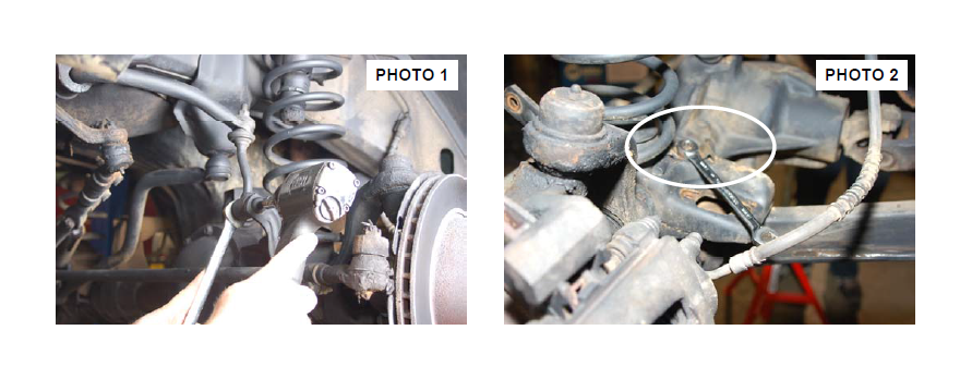
6. Remove the sway bar links from the axle using a 18mm wrench / T55 torx head and a 15mm for the upper and remove the links. See Photo 1.
7. Place a floor jack underneath the axle for support and complete the removal of the front shock absorbers. Using a 13mm socket & wrench remove the lower shock hardware. Retain factory lower mounting hardware for re-use.
8. Remove the track rod from the axle using a 15mm wrench. Retain the hardware for reuse.
9. Remove the coil spring clip located on the bottom coil seat as shown in Photo 2 using a 13mm wrench on the driver side of the vehicle. Lower the axle and remove the coil springs.
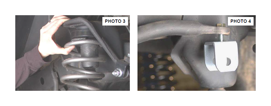
10. With the front axle lowered, install the new front progressive rate coil spring with the supplied 3/4” poly isolator spacer on top as shown in Photo 3. A coil spring or strut compressor may be needed for the new coil spring installation. Install the new progressive coil spring (with the coil wraps that are closer together to the top) into the upper and lower spring pockets and carefully remove the compressor. Make sure the coil is seated properly in the coil seat by rotating the spring so the pig tail end fits in the spring pocket.
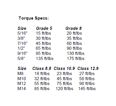
11. Install the coil spring clamp with the stock hardware using a 13mm wrench. Torque the spring clip bolt to 16ft.-lbs.
12. Install the front shock absorber in the factory upper & lower mounts with the stock hardware using a 13mm wrench on the lower mount and a 9/16” on the upper. (RCX 2.2 shocks are highly recommended for this lift).
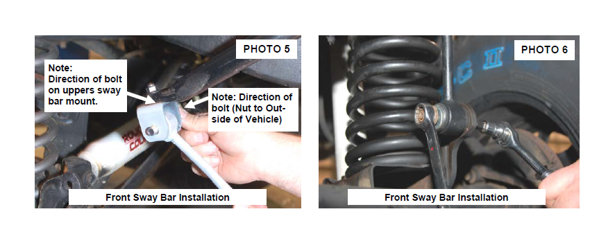
13. Install the supplied sway bar hoop (u—shaped bracket) on the bottom side of front sway bar where the stock link was secured with the supplied 3/8” x 1.25” bolt, washer, and flanged lock nut using a 9/16” wrench. See Photo 4. The bolt will install from bottom to top.
14. Lightly grease and install the 12mm sleeves supplied on the bottom and top of the bent sway bar link.
15. Install the upper part of the new link in the hoop bracket with the 12mm bolts & flanged nut. See Photo 5. Tighten using a 18mm wrench. Note: The bolt must be installed with the nut to outside to provide adequate clearance to the frame.
16. Use the factory hardware to install lower end of link. See Photo 6. Place large face washer between bushing and nut.
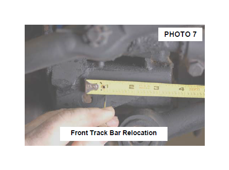
17. On the front track bar mount. Mark as shown in Photo 7 straight over 3/4” from the center of the stock hole and mark using punch. Drill the new track bar hole using a 7/16” drill bit making sure to keep drill level. Do not reinstall the track rod at this time. This will be preformed with the vehicle on the ground. Note: This step will not be performed if the optional Adjustable Track Rod was purchased. If installing the optional track rod, please wait until the vehicle is on the ground to center the front end.
18. Repeat installation on the opposite side of the vehicle.
19. Install the tires, wheels and lug nuts and tighten to factory specifications. Lower the vehicle to the ground. 20. Install the front track rod with the factory hardware. Tighten using a 15mm wrench.
REAR INSTALLATION INSTRUCTIONS
1. Chock the front wheels. Jack up the rear of the vehicle and remove the tires and wheels.
2. Place jack stands under the frame rail to support the vehicle. Place a floor jack under the differential to lightly support the axle.
3. Remove the stock shock absorbers using a 18mm & 15mm wrench on the bottom and a 13mm socket on top. Retain the hardware for reuse.
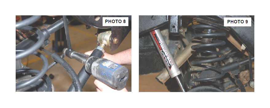
4. Remove the lower sway bar links from the sway bar using a 15mm wrench. See Photo 8 . Retain the factory hardware for re-installation.
5. Remove the track rod from the axle using a T-55 torx head bit.
3. Carefully lower the axle with the floor jack and remove the coil springs. NOTE: It may be necessary to use a coil spring or strut compressor to remove the stock coil springs. Be careful not to overextend the vent tube on the axle. It may be necessary to disconnect the vent tube during installation and reroute the vent tube after installation to ensure the line does not get damaged.
4. Install the new Rough Country progressive rate coil springs with the 3/4” coil spacer on top of the coil spring making sure the stock coil isolator is positioned in the upper mount. It may be necessary to use a coil spring or strut compressor to install the new coil springs. See Photo 9. Rough Country’s New RCX 2.2 series shock is also pictured and highly recommended for this kit.
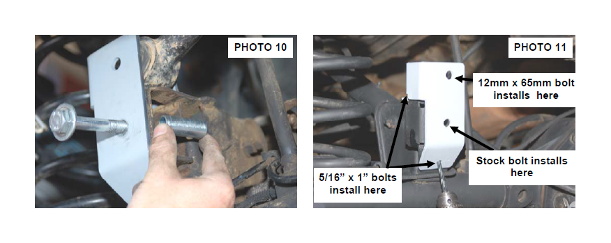
5. Install the new track bar relocation bracket in the stock location. Secure using the factory hardware and supplied sleeve as shown in Photo 10. Tighten using a T-55 Torx Head Bit.
6. Enlarge the 2 holes in the factory lower mount to accommodate the 5/16” bolts, using the bracket hole as a guide. See Photo 11. Install the 5/16” x 1”bolts, washers, lock washers, nuts and tighten using a 1/2” wrench. Do not install the track rod in the new bracket at this time.
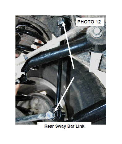
7. On the rear, slightly grease and insert the sway bar bushings and 10mm sleeves in the new rear extended sway bar links. Secure the links to the stock location with the supplied 10mm x 60mm bolt, washers and nuts supplied. See Photo 12. Tighten using a 15mm Socket / Wrench. On the upper mounts you will reuse the factory winged nut with the supplied 10mm x 60mm bolts. Tighten all 10mm bolts to 40 ft. lbs.
8. Jack up the axle to lightly compress the coil springs.
9. Install the rear shock absorber in the factory mounts with the factory hardware using a 15mm & 18mm wrench for the lower and a 13mm socket for the upper. Tighten hardware.
10. Install the wheels and tires and lower the vehicle to the floor.
11. Reinstall the factory sway bar links with the factory hardware using a 15mm wrench and tighten.
12. Reinstall the track bar in the axle mount and secure with the supplied 12mm x 65mm bolt and tighten using a 18mm socket & wrench.
TRANSFER CASE DROP INSTRUCTIONS
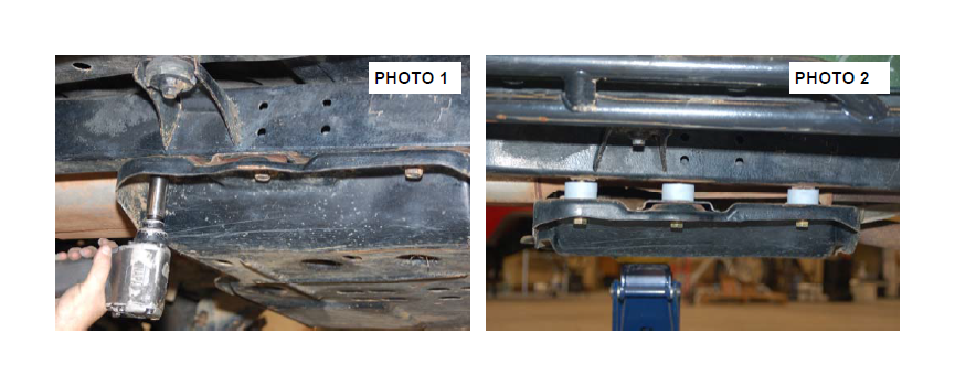
1. Position a floor jack under the transfer case skid plate and remove the stock bolts from the skid plate on one side of the skid plate only. Slightly loosen other side, but do not remove bolts. See Photo 1.
2. Carefully lower the skid plate to allow for installation of the transfer case drop pucks. See Photo 2. Jack up the floor jack and install with the supplied bolts. Tighten bolts using a 3/4” Socket
3. Repeat on other side.
4. On some 03-06 models, in addition to the 3 skid plate bolts ,the vehicle may be equipped with a skid plate for the automatic transmission. For this option, two spacers and two bolts are supplied and the installation procedure is the same.
POST INSTALLATION INSTRUCTIONS
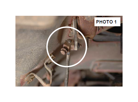
1. Check the transfer case shifter to see if it will move to 4L. If not, the linkage will need adjusting. Place the shifter in 4L, loosen adjustment bolt and push the linkage forward until it stops. Now re-tighten adjustment bolt. See Photo 1. Check to be sure 4WD works properly.
2. Rotate driveshaft and check for interference at differential yoke and cardan joint. If necessary, lightly dress casting(s) and/or U-joint tabs in order to eliminate binding
3. Have a qualified alignment center realign front end to factory specifications.
4. Install Warning to Driver decal on sun visor.
5. Adjust headlights to proper settings.
MAINTENANCE INFORMATION
It is the ultimately the buyers responsibility to have all bolts/nuts checked for tightness after the first 500 miles and then every 1000 miles or 3 months. Wheel alignment steering system, suspension and driveline systems must be inspected by a qualified professional mechanic at least every 3000 miles.
