FREE 1 to 3-Day Delivery on Orders $149+ Details

How to Install Rough Country 2.5 In. Suspension Lift Kit on your 1987-1995 Wrangler

Shop Parts in this Guide
PRODUCT USE INFORMATION
As a general rule, the taller a vehicle is, the easier it will roll. Offset, as much as possible, what is lost in rollover resistance by increasing tire track width. In other words, go "wide" as you go "tall". Many sportsmen remove their mud tires after hunting season and install ones more appropriate for street driving; always use as wide a tire and wheel combination as possible to enhance vehicle stability.
Seat belts and shoulder harnesses should be worn at all times. Avoid situations where a side rollover may occur. Generally, braking performance and capability are decreased when significantly larger/heavier tires and wheels are used. Take this into consideration while driving.
Do not add, alter, or fabricate any factory or after-market parts to increase vehicle height over the intended height of the Rough Country product purchased. Mixing component brands is not recommended. Rough Country makes no claims regarding lifting devices and excludes any and all implied claims. We will not be responsible for any product that is altered.
This suspension system was developed using a 31x10.5 tire on a 15” x 8” wheel with 3.75” of backspacing. If you have any questions concerning the design, function, and/or correct use of our products please contact one of our customer service representatives us at 800-222-7023.
NOTICE TO DEALER AND VEHICLE OWNER
Any vehicle equipped with any Rough Country product should have a “Warning to Driver” decal installed on the inside of the windshield or on the vehicle’s dash. The decal should act as a constant reminder for whoever is operating the vehicle of its unique handling characteristics.
INSTALLING DEALER - it is your responsibility to install the warning decal and forward these installation instructions on to the vehicle owner for review. These instructions should be kept in the vehicle for its service life.
PRE—INSTALLATION INSTRUCTIONS
Prior to beginning this installation it is always good to use a penetrating oil and spray all fasteners that will be removed. Typically the spring eye bolts and the pitman arm are difficult to remove without having done this step.
INSTALLATION INSTRUCTIONS
1. Raise the front of the vehicle and support with safety stands under the frame rails. Take care not to over extend the stock brake lines.
2. Remove the front wheels and tires. Remove stock shocks using a 3/4” wench. Retain the lower shock hardware for reuse.
3. Support the front axle housing with a floor jack (you must have stands under frame supporting vehicle weight).
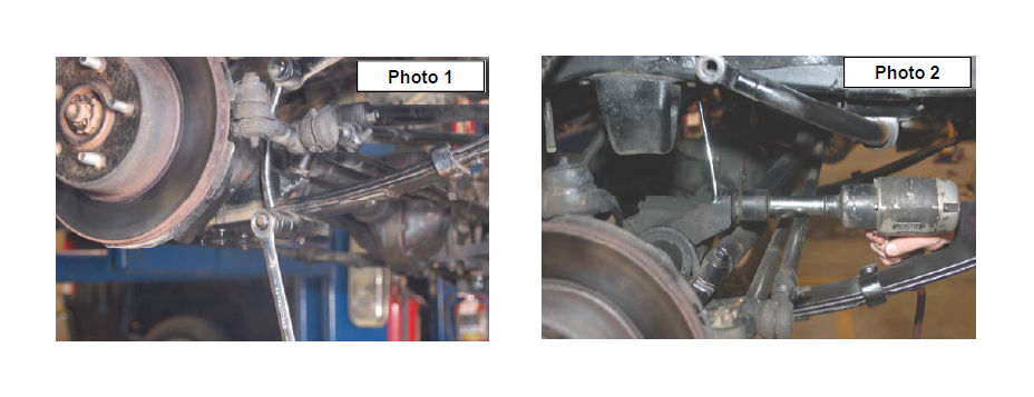
4. Remove the stock sway bar links from the sway bar and the spring pads using a 3/4” wrench. It may be necessary to tap the upper link on the sway bar with a hammer to release the tapered pin. See Photo 1.
5. Unbolt track bar from the housing on the passenger side of the front axle as shown in Photo 2 and then tie the bar up and out of the way.
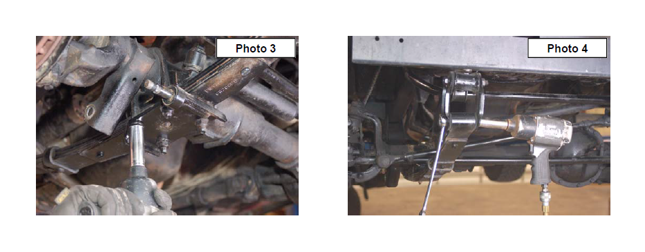
6. Remove the four front spring to axle u-bolts. See Photo 3. (The remainder of the spring removal and installation is performed one side at a time.)
7. On the driver side position a floor jack under the axle tube, just inside of the leaf spring. Raise the jack until the axle just separates from the spring. Now remove the frame bolts and the shackle bolts on the leaf spring using a 3/4” wrench/socket on the shackle end and a 13/16” & 11/16” on the frame end. See Photo 4. Remove the stock spring and retain the stock hardware.
8. Repeat on the other side.
9. Loosely attach the spring (front spring part number is 8009 to its hangers with the stock bolts, washers & nuts. Snug up but do not completely tighten. Make sure spring tie bolt heads align and seat into spring perch holes.
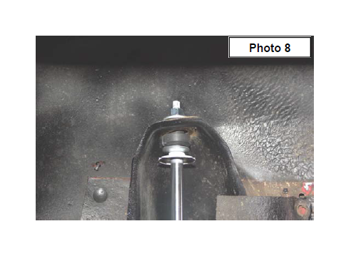
10. Assemble and install new front shock absorbers Part #651896 / 651997 Nitro. Tighten upper stem type mounts using a 9/16” wrench only until the bushings swell slightly – do not over-tighten, torque lower mounts to 45 ft lbs. See Photo 8. Tighten the lower shock bolt with a 3/4” wrench.
11. Do not tighten the springs at this time. The spring hardware will be tightened once the vehicle is on the ground and the suspension has been cycled. Tightening the hardware at this time with the vehicle off the ground could result in a stiff ride.
12. Install tires/wheels, remove jack stands and lower vehicle to floor. Tighten the front spring’s shackle to 95 ft. lbs. and the stationary end to 105 ft. lbs.
13. Reinstall the stock sway bar links with factory hardware. Tighten with a 3/4” wrench.
REAR INSTALLATION INSTRUCTIONS
1. Chock the front tires and jack up the vehicle. Place safety jack stands under rear frame rails.
2. Remove the rear shocks from the shock mounts using a 3/4” wrench on top and bottom. Retain hardware for reuse.
3. Remove the stock u-bolts from the axle using a 3/4” socket
4. With the axle at full droop. Position a floor jack under the axle for support and remove the leaf spring hardware securing the springs to the frame and shackles using a 3/4” wrench for the shackle end and a 13/16 & 11/16 for the frame end. Retain the factory hardware for reuse.
5. Remove the rear springs from the frame mount and the shackles.
6. Install with the stock bolts to the stock location.
7. Install new springs part # 8012 with shims. (torque u-bolts 65 ft. lbs.) When installing the springs the thick part of shim goes toward front of jeep. Do not fully tighten the springs and the track bar to factory specs until the vehicle is on the ground. Tightening before the weight is on the vehicle may prevent the shackles from moving to their natural position and result in the arched spring being pinned forward against the frame.
8. Assemble the rear shock absorbers. Part# 657341 / 657342 Nitro with loop bushings and corresponding sleeves and install shocks, torque upper and lower mounts to 45-ft. lbs using a 3/4” wrench. With the addition of shackles or any other extra lifting device there may not be adequate clearance between the shock body and the axle tube. In this situation your only option is to relocate the shock bracket.
9. Install tires/ wheels.
10. Remove jack stands and lower vehicle to floor. Tighten the shackle to 95 ft. lbs. and the frame end to 105ftlbs.
POST INSTALLATION INSTRUCTIONS
1. Check all fasteners for proper torque. Check to ensure there is adequate clearance between all rotating, mobile, fixed and heated members. Check steering gear for interference and proper working order. Test brakes.
2. Perform steering sweep. Check to ensure brake hoses have sufficient slack and will not contact rotating, mobile, or fixed members, adjust lines/brackets to eliminate interference and maintain proper working order. Failure to perform inspections may result in component failure.
3. If larger tires (10% or larger than stock) are installed, speedometer recalibration is necessary.
4. Bump stops and extensions must be in place on all vehicles! Note: allowing suspension to over extend by neglecting to install or maintain stops and extensions may cause serious damage to related components.
5. Re torque all fasteners after 500 miles. Visually inspect components and re torque fasteners during routine vehicle service.
6. Using an certified alignment professional with experience in aligning lifted vehicles, get an alignment done to factory specifications.
7. Readjust headlights to proper settings.
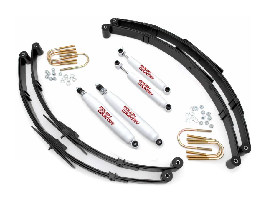
KIT CONTENTS