 FREE 1 to 3-Day Delivery on Orders $149+ Details

How to Install Rough Country 2" Suspension Lift Kit on your 1997-2006 Wrangler
Tools Required
- 13mm Socket / Wrench
- 15mm Socket
- 18mm Socket / Wrench
- 19mm Socket / Wrench
- T55 Torx Head Bit
- 9/16" Socket / Wrench

Shop Parts in this Guide
Thank you for choosing Rough Country for your suspension needs.
Rough Country recommends a certified technician installs this system. In addition to these instructions, professional knowledge of disassemble/reassembly procedures as well as post installation checks must be known. Attempts to install this system without this knowledge and expertise may jeopardize the integrity and/or operating safety of the vehicle. Please read all the instructions before beginning the installation. Check the kit hardware against the parts list. Be sure you have all the needed parts and understand where they go. Also please review the tools needed list and make sure you have needed tools.
PRODUCT USE INFORMATION
As a general rule, the taller a vehicle is the easier it will roll. We strongly recommend, because of rollover possibility, that the vehicle be equipped with a functional roll-bar and cage system. Seat belts and shoulder harnesses should be worn at all times. Avoid situations where a side rollover may occur.
Braking performance and capabilities are decreased when significantly larger/heaver tires and wheels are used. Take this into consideration while driving. Also, speedometer recalibration is necessary when larger tires are installed.
Do not add, alter, or fabricate any factory or after-market parts which increase vehicle height over the intended height of the Rough Country product purchased. Mixing component brands voids all warranties. Rough Country makes no claims regarding lifting devices and excludes any and all implied claims. We will not be responsible for any product that is altered.
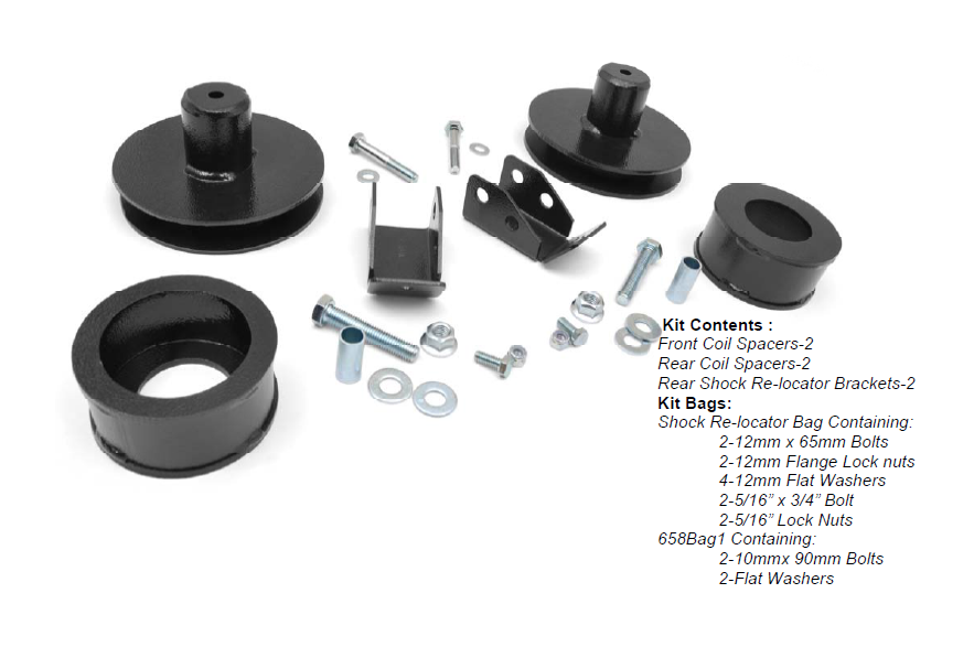
This 2 ” suspension system was developed for 31x10.50x15 tire on an after market 8” wide wheel with 3.75” of back spacing. The use of stock wheels with larger than stock tires may cause the tire to come in contact with the lower control arm at full turn. The use of aftermarket wheels is recommended to avoid this. On models outfitted with extra bolt-on equipment and accessories, Rough Country offers new coil spring isolator pads made from polyurethane to boost ride height 3/4" and these may be needed to maintain a level performance look. Rough Country Hydro shocks are also available for this application.
NOTICE TO DEALER AND VECHICLE OWNER
Any vehicle equipped with any Rough country product must have the “Warning to Driver” decal installed on the sun visor or dash. The decal is to act as a constant reminder for whoever is operating the vehicle of its unique handling characteristics. INSTALLING DEALER—It is your responsibility to install the warning decal and to forward these installation instructions on to the vehicle owner for review and to be kept in the vehicle for its service life.
FRONT INSTALLATION INSTRUCTIONS
1. The front-end components are installed first.
2. Place the vehicle on a level surface. Set the parking brake. Center the front wheels and chock rear wheels.
3. From inside the engine compartment, remove the upper stud nut, retainer and grommet from both of the front shocks using a 9/16” wrench.
4. Place jack stands on the frame rail behind the lower control arm mount on the frame and jack up the vehicle. Installation is done one side at a time.
5. Remove the front tires and wheels.
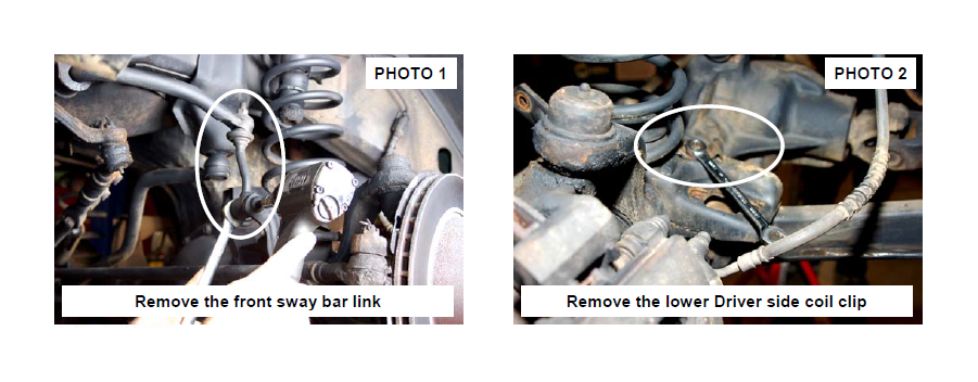
6. Remove the sway bar links from the axle using a 18mm wrench / T55 torx head bit to allow the axle to be lowered for coil spring removal. See Photo 1.
7. Place a floor jack underneath the axle for support and complete the removal of the front shock absorbers using a 13mm socket. Retain factory lower mounting hardware for re-use.
8. Remove the coil spring clip located on the bottom coil seat as shown in Photo 2 using a 13mm wrench on the driver side of the vehicle. Lower the axle and remove the coil spring.
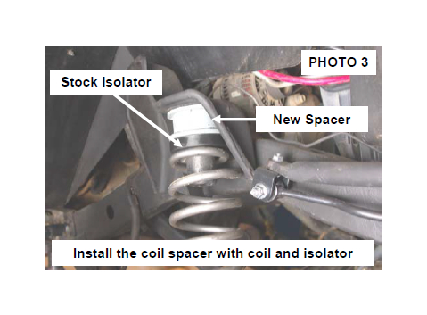
9. Reinstall the coil spring as shown in Photo 3 with the stock spring isolator in between the stock coil and the new spacer on top.
10. Reinstall the coil slip using a 13mm wrench on the driver side.
11. Repeat installation on the opposite side of the vehicle.
12. Install the tires, wheels and lug nuts and tighten to factory specifications. Lower the vehicle to the ground.
13. Reinstall the shock absorbers using a 9/16” wrench on the upper and a 13mm wrench on the lower mount.
14. Reinstall the sway bar links in the factory location with factory hardware using a 18mm wrench and T55 torx head bit.
REAR INSTALLATION INSTRUCTIONS
1. Chock the front wheels. Jack up the rear of the vehicle and remove the tires and wheels.
2. Place jack stands under the frame rail to support the vehicle. Place a floor jack under the differential to lightly support the axle.
3. Remove the shock absorbers from the lower mount using a 18mm & 15mm wrench. Retain hardware for reuse.
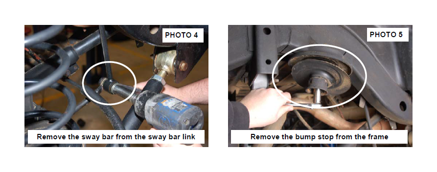
4. Remove the lower sway bar links from the sway bar using a 15mm wrench. See Photo 4 . Retain the factory hardware for re-installation.
5. Carefully lower the axle with the floor jack and remove the coil springs. NOTE: It may be necessary to use a coil spring compressor to remove the stock coil springs. Be careful not to overextend the vent tube on the axle. It may be necessary to disconnect the vent tube during installation and reroute the vent tube after installation to ensure the line does not get damaged.
6. Remove the bump stop from the bump stop mount and remove the bump stop cup as shown using a 15mm socket. See Photo 5. Retain the stock hardware and upper coil isolator.
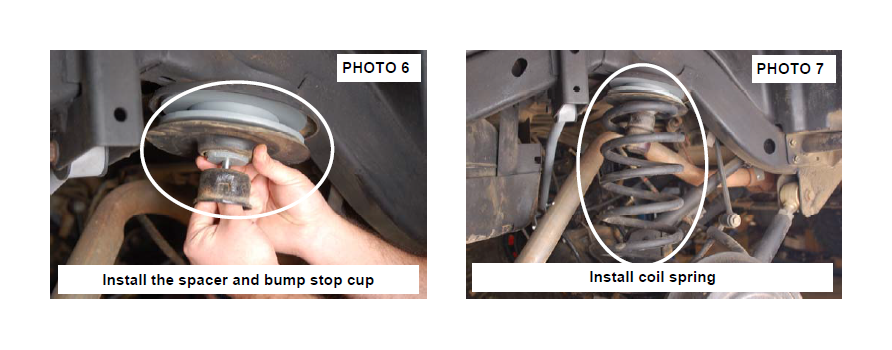
7. Install the spacer and bump stop cup on the upper coil mount with the supplied 10mm x 90mm bolts /washers. See Photo 6. Tighten using a 17mm socket. Reinstall the bump stop in the bump stop cup.
8. Re-install the coil isolator on the spacer and install the spring on the mount. See Photo 7. It may be necessary to use a coil spring or strut compressor to install the new coil springs.
9. Jack up the axle to lightly compress the coil springs.
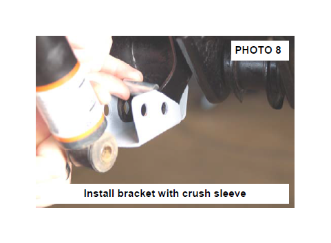
10. Install the lower shock bracket as shown in Photo 8 with the supplied 12mm x 65mm bolts, flange locknuts with supplied crush sleeves Do not tighten at this time.
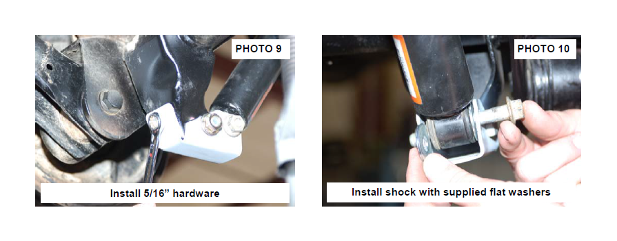
11. Install the 5/16” x 3/4” bolts, washers & nuts as shown in Photo 9. Tighten the 12mm bolts using a 19mm wrench & 18mm socket. Tighten the 5/16” bolts using a 13mm socket and wrench.
12. Install the wheels / tires and lower the vehicle to the floor.
13. Install the rear shock absorber in the factory upper and lower mounts with the factory upper / lower hardware and the supplied flat washers. See Photo 10. Tighten using a 15mm & 18mm wrench for the lower and a 13mm socket for the upper.
14. Reinstall the factory sway bar links with the factory hardware using a 15mm wrench and tighten.
POST INSTALLATION INSTRUCTIONS
1. Check all fasteners for proper torque. Check to ensure for adequate clearance between all rotating, mobile, fixed, and heated members. Verify clearance between exhaust and brake lines, fuel lines, fuel tank, floor boards and wiring harness. Check steering gear for clearance. Test and inspect brake system.
2. Have a qualified alignment center align the vehicle immediately. Realign to factory specifications. Have headlights adjusted to proper settings.
6. Perform head light check and adjustment to proper settings.
7. Check and retighten wheels at 50 miles and again at 500 miles.
8. All kit components must be retightened at 500 miles and then every three thousand miles after installation. Periodically check all hardware for tightness.
9. Install “Warning to Driver” decal on sun visor. Note: Installation of larger tires will require speedometer recalibration.

