 FREE 1 to 3-Day Delivery on Orders $149+ Details

How to Install Poison Spyder Trail Corner Guards w/ Round Tail Light & Backup Light Cutouts - SpyderShell Armor Coat on your Wrangler
Tools Required
- Phillips head & small flat head screwdrivers
- Welding clamps or C-clamps
- Measuring tape
- Drill motor, 5/16” & 25/64” drill bits
- Fine tip felt marker
- Touch-up paint or clear coat
- 5/8” open end wrench
- 5/32” hex key or driver bit
- 2-3/4” hole saw (optional, if installing 2-1/2” LED backup lamps)
- OPTIONAL: Professional Nut-Sert Install Tool

Shop Parts in this Guide
APPLICATIONS
These installation instructions apply to the following Poison Spyder products:
18-06-020P1 JK 4-Dr Trail Corners - LED Taillights - Black
18-06-021P1 JK 4-Dr Trail Corners - LED Tail & Backup Lights - Black
18-06-022P1 JK 4-Dr Trail Corners - OEM Taillights - Black
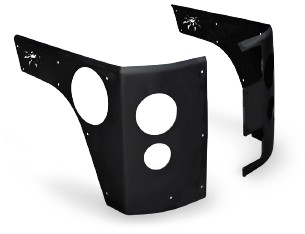
PARTS LIST
(1) Right Side JK Trail Corner
(1) Left Side JK Trail Corner
(1)* JK Trail Corner Hardware Kit
PN: HWKIT-18-06-020 includes:
(23) 1/4-20 X 1 SS Button Head Cap Screw
(23) 1/4-20 Nut-Sert
(1) 1/4” Nut-Sert Install Tool - includes:
(1) 1/4-20 X 2 Gr8 Hex Head Cap Screw
(2) 1/4” SAE Hardened Flat Washer
(1) 3/8-16 X 1-1/8 Coupling Nut
(1) 1/4-20 Nut-Sert
INSTALLATION PROCEDURE
1. Park vehicle on a level surface and set the emergency brake. You will want to wear eye protection beyond this point in time.
2. Begin with the driver’s side Trail Corner installation. The procedure for both sides is nearly identical, with a few small differences, which will be denoted in the following steps.
3. Remove the license plate and license plate mount. The wiring for the license plate light will need to be un-plugged.
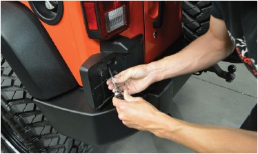
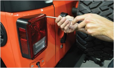
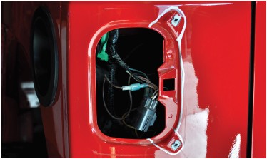
4. Use a Phillips screwdriver to remove the stock taillight assembly from the Jeep. Note that there are four screws, one in each corner of the taillight housing. You only need to remove the two inboard screws. Once these two screws are removed, grip the taillight assembly, slide it slightly toward the center of the Jeep and pop it out.
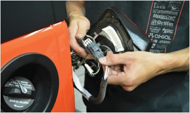
5. With your thumb, press on the release tab of the taillight harness plug, and separate it from the vehicle harness. Set the OE taillight assembly aside.
NOTE: The next 3 steps pertain to Trail Corners with LED taillight holes. If installing Trail Corners made for use with the stock taillights, skip the next 3 steps.
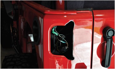
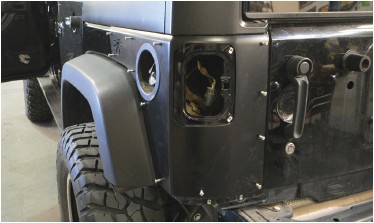
6. Observe the Jeep’s body sheetmetal around the taillight opening. Note that there are two raised areas in the upper right and lower right corners (for the driver’s side taillight--opposite for the passenger side), where the threaded inserts for the taillights are installed. These raised areas, along with the indented flange section between them along the right vertical edge of the taillight hole, will have to be removed for proper fitment of the Trail Corner and clearance for the LED taillight. Use a fine-tip felt marker to outline the area to be removed, as shown in Figure 3.
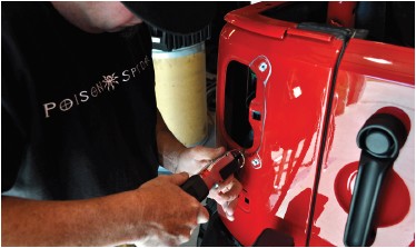
7. Use the tools of your choice to cut the body sheetmetal along your cut mark. Note that part of the cut goes through double-thick sheetmetal and may be difficult to get through. A pneumatic body saw or cut-off wheel may be ideal for this task.
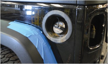
8. Use a file or sander to smooth the edges of the cut sheetmetal. It is important to remove any burrs or sharp edges which may snag, fray or cut electrical wires over time. Use some touch-up paint or clear-coat to seal the bare metal around the edge of the cut, to protect it from rust in the future.
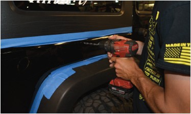
9. Place masking tape around the edges of the area the Trail Corner will cover, to protect the Jeep’s paint during the installation process, as well as the rear fender flares.
10. Place one of the Trail Corner sides over the corner of the Jeep. Use a measuring tape to ensure that the distance between the top edge of the Trail Corner and the top edge of the Jeep’s tub is the same from front to back, and securely clamp the Trail Corner into place. It is important to ensure that the Trail Corner is securely clamped into place, that it won’t loosen the clamps once you begin drilling.

When working on the driver’s side, the Trail Corner will slip snugly over the fuel filler trim piece (and stock taillight housing, if present), assisting with aligning it.
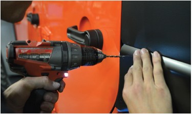
11. Use the 5/16” bit and drill motor to drill through the Jeep’s outer sheetmetal at each of the hole locations in the Trail Corner, using the Trail Corner itself as your drill guide. If the Trail Corner shifts or the clamps loosen while you’re drilling, stop drilling and re-align the Trail Corner and re-clamp it, making sure it still aligns with the holes already drilled.
12. If installing Trail Corners with holes for 2-1/2” backup lamps, use the fine-tip felt marker to mark these holes to be cut later.
13. Un-clamp and remove the Trail Corner, then use the 25/64” drill bit to open up each of the holes to the larger size. Be careful when drilling, as the thin sheetmetal may want to catch on the bit and deform it, making the subsequent nut-sert installation more difficult.
14. If installing Trail Corners with holes for 2-1/2” backup lamps, cut these holes now at the locations that were marked in Step 9. A 2-3/4” hole saw works best for this.
15. Install a 1/4-20 nut-sert into each of the holes that were drilled out to 25/64”.
NOTE: It is HIGHLY RECOMMENDED to invest in a professional nut-sert installation tool, such as the one sold by Poison Spyder (p/n: 70-TS-325-RN ) or elsewhere.
The professional tool will make the installation of nut-serts MUCH easier than using the free tool included in this kit, and it will come in handy with future product installations as well. If using a professional nut-sert installation tool, follow the directions that came with the tool and skip the next three steps of these instructions. The simple “tool” included with this product is admittedly frustrating to use, however it will work for those with patience who would like to save the cost of the professional tool. If using the simple tool included with this product, continue through the following steps:
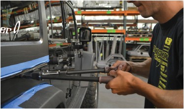
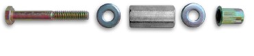
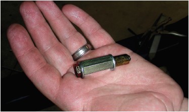
16. The provided nut-sert install tool consists of a bolt, two washers and a coupler (long) nut. Assemble these items as shown (bolt-washer-coupler nut-washer-nut-sert). Insert the nut-sert end of the assembly into the hole you drilled.
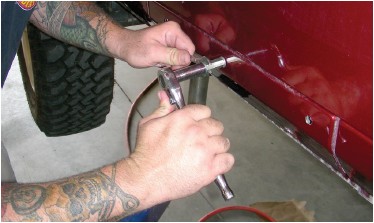
17. Use an open end wrench to hold the coupler nut stationary while turning the head of the bolt clockwise with a ratchet (or small impact wrench) and socket. As you turn the ratchet, the bolt will draw the far end of the nut-sert toward the inside of the sheet metal, gripping it with the knurled outside edge of the nut-sert as it deforms. Continue to turn the ratchet until the nut-sert is fully seated. DO NOT OVER-TIGHTEN as you can damage the nut-sert, or cause it to lose its grip.
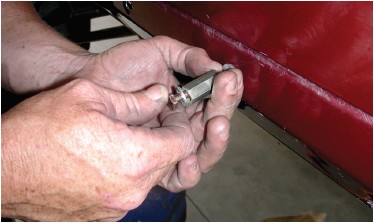
18. Once the nut-sert has seated correctly, loosen the bolt then remove it and the rest of the tool from the nut-sert. Install a new nut-sert onto the tool, oriented the same as the last, and set it aside until your next nut-sert installation.
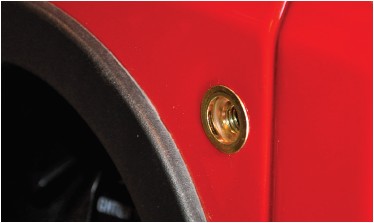
19. With the tool removed, inspect the nut-sert to make sure it is properly seated and that the surrounding sheet metal isn’t excessively deformed. Note that some deformation of the sheet metal is normal, and that it will be covered by the part after installation.
If you “spin” a nut-sert: That is, if it loses its grip due to over-tightening or improper installation, the quickest, easiest fix is to use a MIG welder to place a small tack weld at the edge of the nut-sert flange. Before applying the tack weld, sand or grind the paint from a very small area of the sheetmetal where the tack weld will be. Then insert a screw into the nut-sert to protect the threads from weld splatter. Only apply a very small tack or two, as you do not want to heat up and deform the nut-sert or the sheetmetal. Then grind the tack(s) smooth and apply touch-up paint to prevent rust.
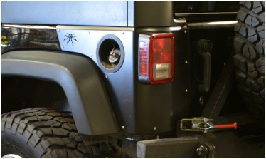
20. Re-Install the finished Trail Corners using the supplied stainless steel button head hardware.
IMPORTANT! Do NOT over-tighten the button head cap screws, as you may accidentally “spin” the Nut-Sert if you over-tighten!
21. Repeat the previous steps for the remaining side.
22. If re-using the OE taillights and license plate mount, reinstall them by reversing the removal procedures from the beginning of these instructions.
23. If installing the Trail Corners designed for the stock taillights, and you are-using the stock license plate mount, reinstall it. If moving the license plate to a different location such as the center of the spare tire, Poison Spyder’s JK Rear License Plate Delete Cover (p/n 17-04-112, sold separately) may be used to fill the hole left by removing the stock license plate mount.
24. If installing LED taillights, follow the instructions that came with them for proper wiring.
Congratulations, you have completed the installation of your Poison Spyder JK Trail Corners!

