 FREE 1 to 3-Day Delivery on Orders $149+ Details

How to Install a Magnaflow Off Road Pro-Series Catback Exhaust on your 2012-2017 Wrangler JK 2 Door

Shop Parts in this Guide
Warning:
When working on, under, or around any vehicle exercise caution. Please allow the vehicle's exhaust system to cool before removal, as exhaust system temperatures may cause severe burns. If working without a lift, always consult vehicle manual for correct lifting specifications. Always wear safety glasses and ensure a safe work area. Serious injury or death could occur if safety measures are not followed.
** Magnaflow Performance Exhaust recommends professional installation on all their products
Step 1:
(Carefully read all instructions before installation)
To remove the OEM exhaust system, unbolt the clamps at the inlet and over-axle pipe, disengage the welded hangers from the rubber insulators and remove the components.
Step 2:
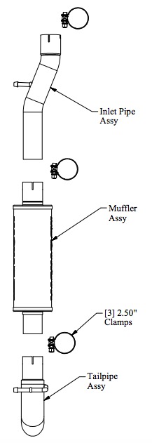
Begin installation of the new system by fitting the new Inlet Pipe Assembly to the catalytic converter, fitting the hanger into the rubber insulator, and by fastening it with a supplied 2.50" clamp. Be sure to fit the alignment peg in the large notch and to leave the clamp loose for final adjustment of the complete system. Install the Muffler and Tailpipe Assemblies in the same fashion.
Step 3:
With all components mounted loosely, adjust the system for overall aesthetics and clearance of frame & bodywork. (MAGNAFLOW recommends at least 1/2" of clearance between the exhaust system and any body panels to prevent heat-related body damage or fire.)
Step 4:
Once a final position has been chosen for the new system, evenly tighten all fasteners from front to rear. The supplied band clamps must be VERY tight to properly align the pipes and prevent leaks (Approximately 40ft-lbs). Inspect all fasteners after 25-50 miles of operation and retighten if necessary.
