 FREE 1 to 3-Day Delivery on Orders $149+ Details

How to Install Baer 14 in. Front Pro+ Brake Kit (07-18 Wrangler JK) on your Jeep Wrangler

Shop Parts in this Guide
ATTENTION: Read this before going any farther! Returns will not be accepted for ANY installed PART or ASSEMBLY. Use great care to prevent cosmetic damage when performing wheel fit check. In the event that a product must be returned, please contact Baer Customer Service for a RMA Number.
Notices – Read and Follow BEFORE ATTEMPTING INSTALLATION
All installations require proper safety procedures and protective eyewear.
All installations assume basic mechanical skill and a factory service manual for the vehicle on which the installation is to be performed.
All references to the “left” side of the vehicle correlate to the driver’s side of the vehicle.
Any installation requiring you to remove a wheel or gain access under the vehicle requires use of jack stands appropriate to the weight of the vehicle. In all cases, jack stands rated for a minimum of 2-tons is recommended.
A selection of hand tools sufficient to engage in the installation of these products is assumed, and is the responsibility of the installer to have in his/her possession prior to beginning this installation. All installations, which require removal of hydraulic hoses and/or bleeding of the brakes, require appropriate fitting/line wrenches, safety catch can, and protective eyewear. Other than these items, if unique or special tools are required they will be stated appropriately in the installation step.
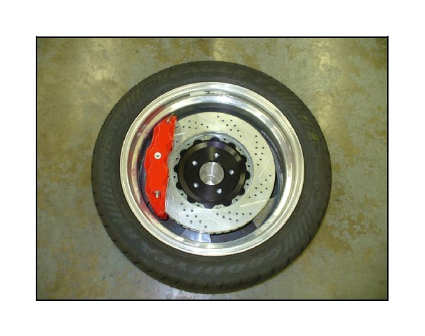
ALWAYS CONFIRM WHEEL FIT PRIOR TO BEGINNING INSTALLATION OF ANY BRAKE SYSTEM OR “UPSIZED” ROTOR UPGRADE! In addition to checking wheel fitment (available online at www.baer.com), always place the actual corner assembly or a combination of the caliper assembly onto the rotor, and into the actual wheel. This procedure will reconfirm proper clearance between the caliper and the wheel before proceeding with the actual installation.
Returns will not be accepted for systems that have been partially or completely installed. Use extreme care when checking wheel fitment to prevent any cosmetic damage.
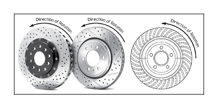
When installing rotors on any Baer Products be sure to follow the direction of rotation indicated on the rotor hat area with either an arrow, or an “L” for left, or an “R” for right, or both. “L” or left always indicates the driver’s side of US spec vehicles. Images shown are “L” left rotors:
A proper professional wheel alignment is required for any system requiring replacement of the front spindles, or tie rod ends. Follow factory prescribed procedures and specifications unless otherwise indicated.
At all times stop the installation if anything is unclear, or the parts require force to install. Consult directly with Baer Technical Staff in such instances to confirm details. Please have these instructions, as well as the part number machined on the component that is proving difficult to install, as well as the make, model, and year (date of vehicle production is preferred) of your vehicle available when you call. Baer’s Tech Staff is available from 8:30-am to 5-pm Mountain Standard Time (Arizona does not observe Daylight Savings Time) at 602 233-1411 Monday through Friday.
INSTALLATION:
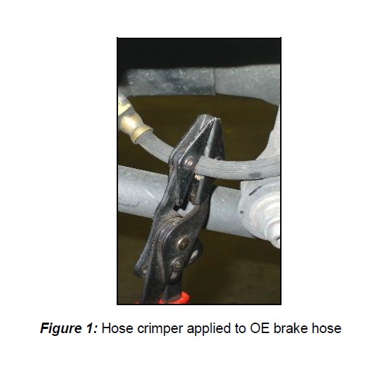
1. Carefully remove the banjo bolt and copper crush washers from the OE brake hose that is attached to the caliper. Do not reuse the copper crush washers as they are one-time use items. To prevent brake fluid dripping from the hose, a pair of hose crimpers can be applied. Do not use vise grip pliers as these may damage the brake hose. See Figure 1 for reference:
2. Remove the bolts retaining the factory caliper. These are tight which may require the use of a long wrench or a breaker bar to allow for easier removal. Once the bolts are removed, slide the caliper off the rotor.
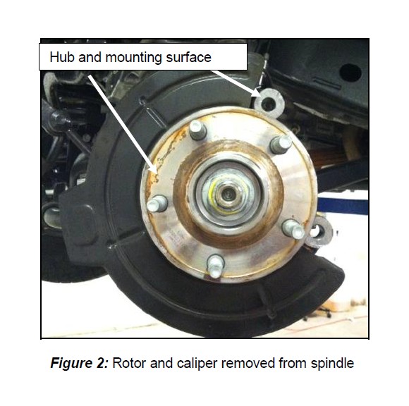
3. Remove the rotor and thoroughly clean the hub surface and caliper mounting surfaces to ensure proper seating of the new components. See Figure 2 for reference.
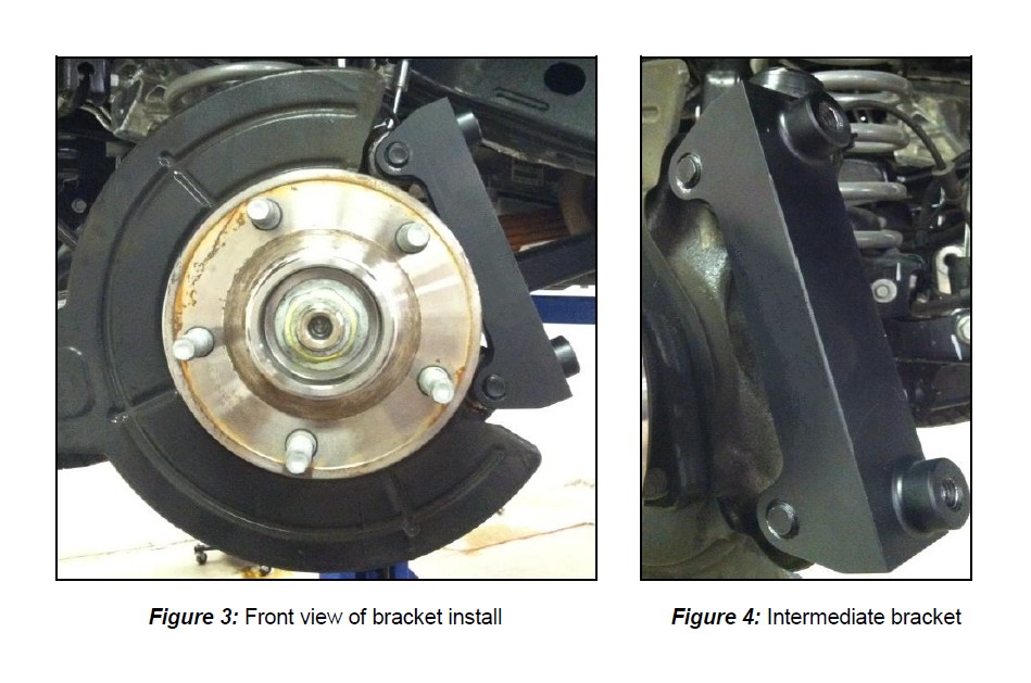
4. Install the intermediate bracket to the outboard side of the spindle using the supplied M14-2.0x45 Hex bolts and washers. The bracket will bolt onto the spindle with its part number facing inboard. Torque each bolt to 120 ft∙lbs. See Figures 3 and 4 for reference.
**Note: The removal of the dust shield is not required as it will not interfere with the new rotor.
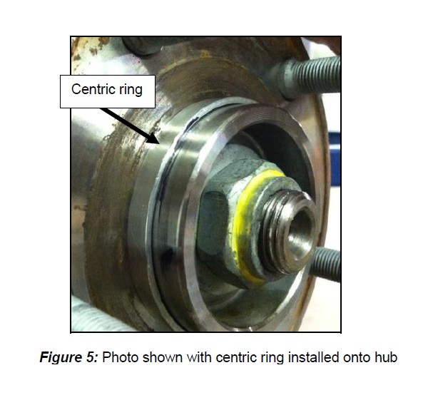
5. Next, install the centric ring onto the hub (for PRO system only). This can be accomplished by simply sliding the ring over the hub snout until it sits firm against the hub face. **Note: Ensure the ring is centered and level when sliding it over the hub snout. See Figure 5 for reference:
6. Install the correct side rotor onto the hub and secure with three lug nuts and washers to prevent scratching the hat.
7. With brake pads installed, install the new caliper onto the bracket and secure with the supplied M12-1.75x45 Socket Head bolts. Torque each bolt to 75 ft∙lbs.
8. The final step is to install the OE brake hose into the new caliper using the new banjo bolts and crush washers. Replace the OE banjo bolt and crush washers with the new supplied banjo bolt and crush washers. **Note: One crush washer must be placed on each side of the banjo bolt to prevent brake fluid from leaking out of the hose. Once complete, carefully thread the banjo bolt into the rear of the caliper. **IMPORTANT: Position the hose to avoid interference with the wheel and suspension components through the entire range of motion. Torque the banjo bolt between 15-20 ft∙lbs. Remove the hose crimpers so that the fluid is able to travel freely through the hose.
9. Repeat these steps for the other side and recheck all attachment points and fittings.
Refer to Bleeding, and Pad Bedding & Rotor Seasoning Procedures contained on a separate sheet, or on www.baer.com
For service components and replacement parts contact your Baer Brake Systems Tech Representative.

