FREE 1 to 3-Day Delivery on Orders $149+ Details

How to Install ARB High Output Air Compressor (87-17 Wrangler YJ, TJ, & JK) on your Jeep Wrangler
Installation Time
3 hours
Tools Required
- Sockets:10mm
- Socket wrench
- Crescent wrench
- 4mm Allenwrench
- Wire cutter/stripper
- Electrical tape
- Teflon tape
- Zip ties
- Jackand jack stands(Helpful, not required)
- Screwdriver

Shop Parts in this Guide
Note: This install will require a mounting bracket for your desired mount location. I will be using the Evo under hood mount bracket. Also, if you will be using this to inflate tires you will need the ARB Tire Inflator Kit.
Note: This install will require a mounting bracket for your desired mount location. I will be using the Evo under hood mount bracket. Also, if you will be using this to inflate tires you will need the ARB Tire Inflator Kit.
Before Picture:
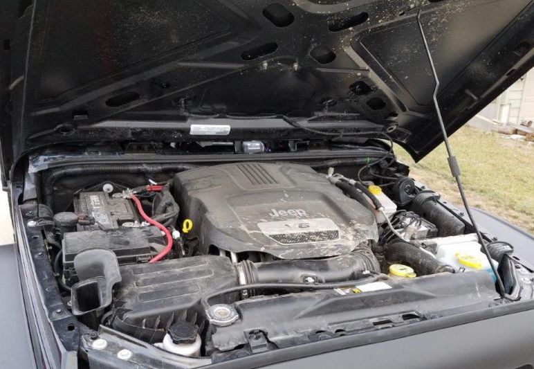
Before Picture:
Wiring Details:
Wiring Details:
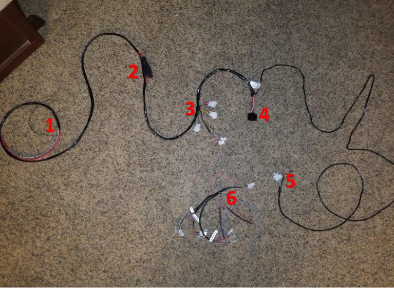
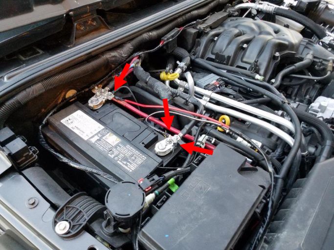
1. The power wires to the battery. Connect Red to positive, and both black wires to Negative.
2. The in-line fuse.
3. Solenoid connections. See next photo.
4. Relay connector.
5. Unassembled harness (can be pushed through a small hole in the firewall before putting the connector together)
6. Switch connections. See 3rd photo.
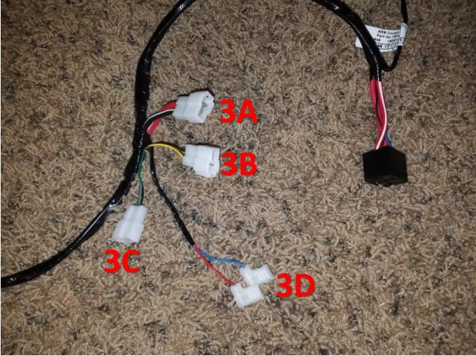
3A: Compressor power. Connects directly to connector on compressor.
3B: Connects to solenoid 1 (not included)
3C: Connects to solenoid 2 (not included)
3D: Connects to pressure switch.
3A: Compressor power. Connects directly to connector on compressor.
3B: Connects to solenoid 1 (not included)
3C: Connects to solenoid 2 (not included)
3D: Connects to pressure switch.
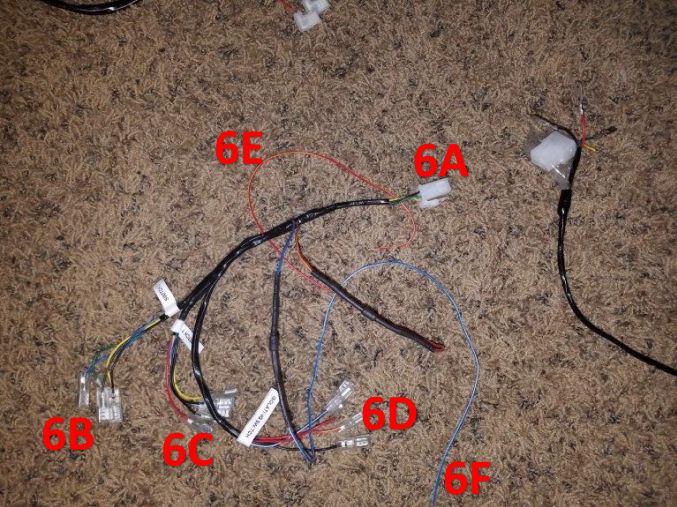
6A: Connects to #5 in the first photo.
6B: Connects to switch 2 (Controls solenoid 2)
6C: Connects to switch 1 (Controls solenoid 1)
6D: Connects to compressor control switch.
6E: Red-Yellow wire, connects to an ignition source.
6F: Blue-White wire, connects to dash illumination.
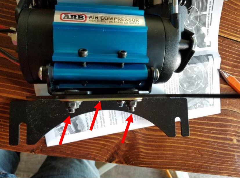
1. Using a 10mm socket, the supplied hardware and backer plate, attach the ARB compressor to your mounting bracket
6A: Connects to #5 in the first photo.
6B: Connects to switch 2 (Controls solenoid 2)
6C: Connects to switch 1 (Controls solenoid 1)
6D: Connects to compressor control switch.
6E: Red-Yellow wire, connects to an ignition source.
6F: Blue-White wire, connects to dash illumination.
1. Using a 10mm socket, the supplied hardware and backer plate, attach the ARB compressor to your mounting bracket
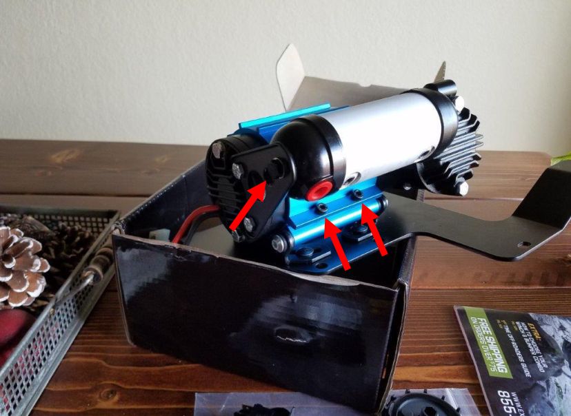
2. To adjust the configuration of your compressor, use a 4mm allen wrench to loosen the 2 screws shown below. Then you can rotate the compressor as necessary. You can also use a 10mm socket to loosen the bolt on the side of the air tank. You can then rotate the air tank to put the air port where you want.
2. To adjust the configuration of your compressor, use a 4mm allen wrench to loosen the 2 screws shown below. Then you can rotate the compressor as necessary. You can also use a 10mm socket to loosen the bolt on the side of the air tank. You can then rotate the air tank to put the air port where you want.
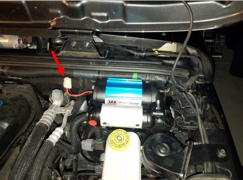
3. Next, mount the compressor bracket following the instructions for your specific bracket. Then attach connector 3A from the wiring photos to the compressor power plug shown below.
3. Next, mount the compressor bracket following the instructions for your specific bracket. Then attach connector 3A from the wiring photos to the compressor power plug shown below.
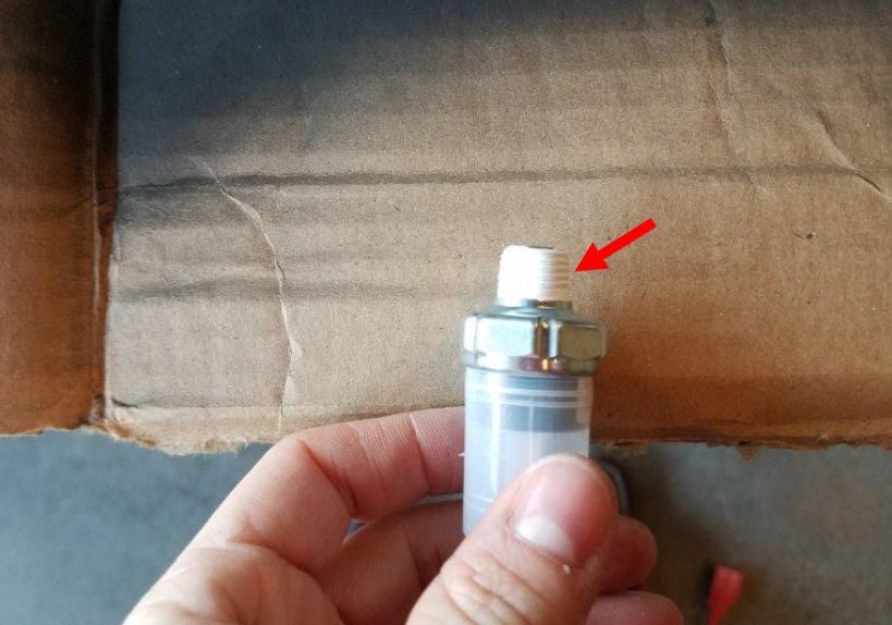
4. Remove the small red cap and screw on the supplied air filter as shown below.
4. Remove the small red cap and screw on the supplied air filter as shown below.
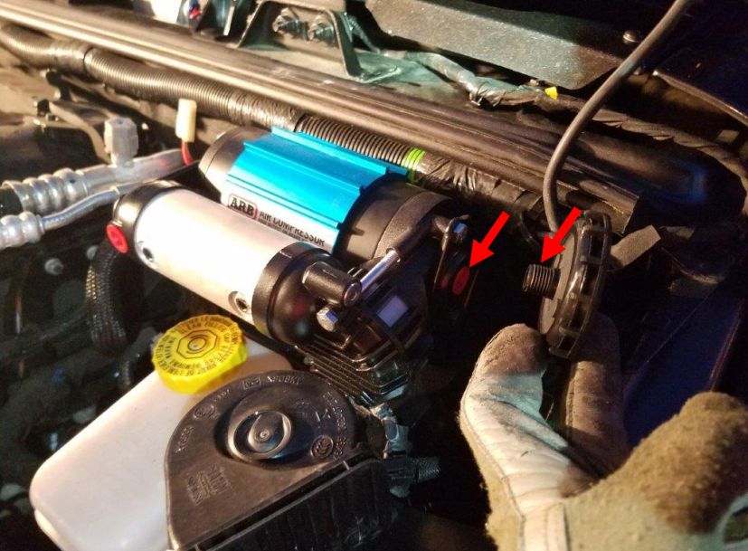
5. Wrap Teflon tape tightly around the threads on the supplied pressure switch.
5. Wrap Teflon tape tightly around the threads on the supplied pressure switch.
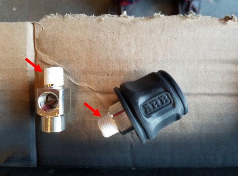
6. Note: These parts come with the inflator kit. Wrap teflon tape around the threads of the inflator kit parts shown below.
6. Note: These parts come with the inflator kit. Wrap teflon tape around the threads of the inflator kit parts shown below.
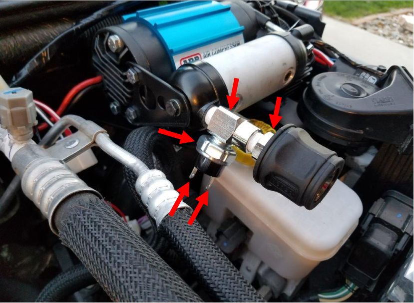
7. Remove the red cap then screw on the inflator parts and pressure switch as shown below. Use a crescent wrench to make sure they are all tight so you don’t have air leaks. Then attach the 3D connectors to the pressure switch terminals. It doesn’t matter which connector goes on which pin. Note: You can put these parts in any configuration you’d like.
7. Remove the red cap then screw on the inflator parts and pressure switch as shown below. Use a crescent wrench to make sure they are all tight so you don’t have air leaks. Then attach the 3D connectors to the pressure switch terminals. It doesn’t matter which connector goes on which pin. Note: You can put these parts in any configuration you’d like.
8. Attach the supplied terminals to the #1 power wires. I recommend soldering them for a lasting connection.
8. Attach the supplied terminals to the #1 power wires. I recommend soldering them for a lasting connection.
9. Then route the wires as necessary to keep them away from moving/hot parts. I recommend you zip tie them to the stock cables running along the top of the firewall. Then connect the red wire to the positive terminal, and both black wires to the negative terminal.
9. Then route the wires as necessary to keep them away from moving/hot parts. I recommend you zip tie them to the stock cables running along the top of the firewall. Then connect the red wire to the positive terminal, and both black wires to the negative terminal.
10. Depending on how you want your switch setup you will have a few different options.
a. If you will use the supplied switch placed in the dash you will need to run the #5 connector through the firewall to where your switch is. Then put that connector together. Attach the #6 wire harness to the #5 connector. Then attach 6D to the switch. Red to pin 3, red/yel to pin 2, black to pin 8 and 7, blue/wht to pin 6.
b. If you will be using a switch pod (such as S-Pod, or the Rough Country MLC-6), complete step 11 and 12.
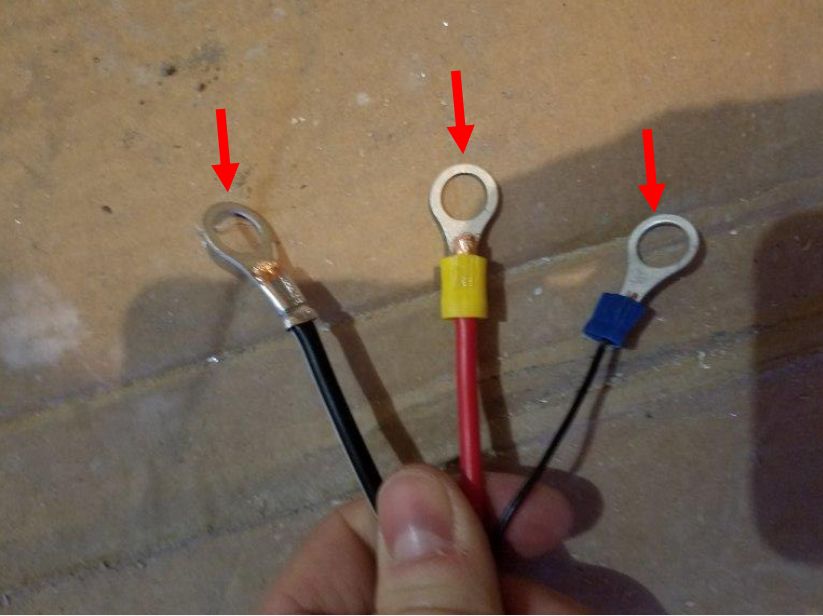
11. For this setup, you will not need the #6 harness. You will not assemble the #5 connector. Instead, you cut off the pins on the wires at connector #5, and replace them with U-terminals as shown below. You will use black and red for the compressor switch, yellow for the solenoid 1 switch, and green for the solenoid 2 switch. Note: If not using solenoids you do not need the yellow and green wires.
10. Depending on how you want your switch setup you will have a few different options.
a. If you will use the supplied switch placed in the dash you will need to run the #5 connector through the firewall to where your switch is. Then put that connector together. Attach the #6 wire harness to the #5 connector. Then attach 6D to the switch. Red to pin 3, red/yel to pin 2, black to pin 8 and 7, blue/wht to pin 6.
b. If you will be using a switch pod (such as S-Pod, or the Rough Country MLC-6), complete step 11 and 12.
11. For this setup, you will not need the #6 harness. You will not assemble the #5 connector. Instead, you cut off the pins on the wires at connector #5, and replace them with U-terminals as shown below. You will use black and red for the compressor switch, yellow for the solenoid 1 switch, and green for the solenoid 2 switch. Note: If not using solenoids you do not need the yellow and green wires.
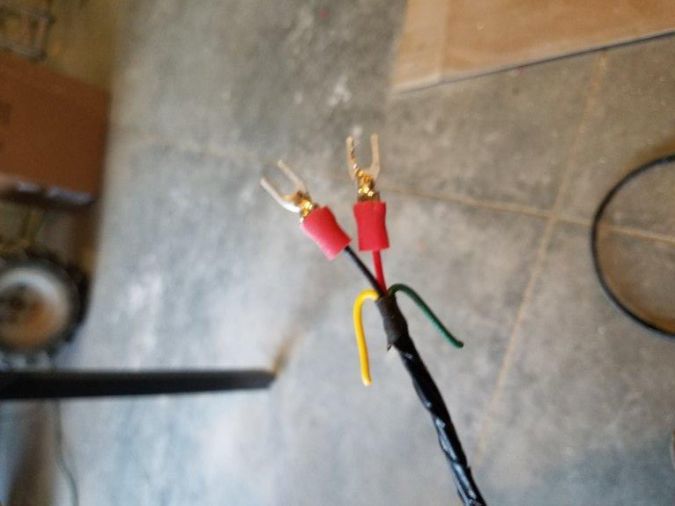
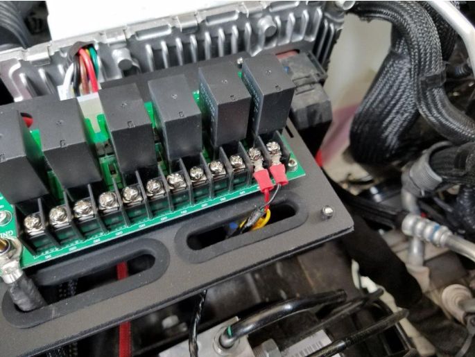
12. Connect the wires from step 11 to your switch pod terminals, red to positive, black to negative. If using the solenoids connect the yellow or green wire to the positive terminal of the desired switch, but negative is not needed.
12. Connect the wires from step 11 to your switch pod terminals, red to positive, black to negative. If using the solenoids connect the yellow or green wire to the positive terminal of the desired switch, but negative is not needed.
13. If you used the switch setup from step 10a, you will also need to connect the wires 6E, and 6F to the ignition, and dash illumination respectively.
14. Turn your ignition on, and test to make sure your compressor turns on. If no air drain is connected it should turn on momentarily, then turn off. This means the pressure switch is working properly. You can also listen for any air leaks, and tighten it up as needed.
After Picture:
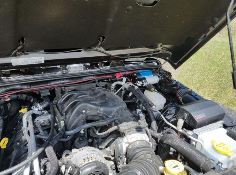
After Picture: