FREE 1 to 3-Day Delivery on Orders $149+ Details

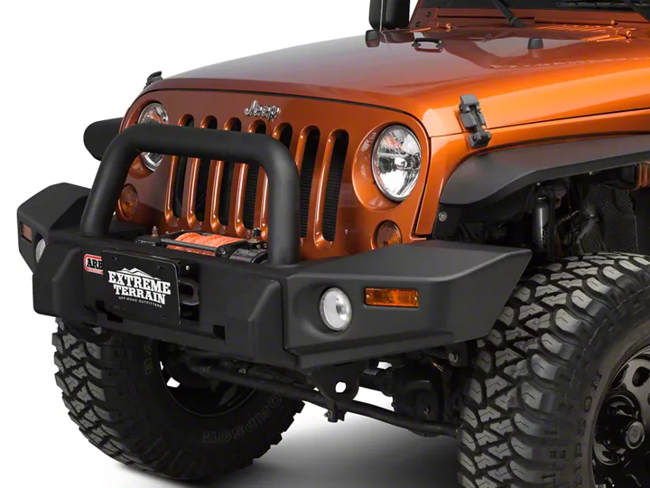
How to Install an ARB Front Bumper with Bullbar on your 07-18 Jeep Wrangler JK; 2018 Jeep Wrangler JL
Installation Time
2 hours
Tools Required
- Basic tool kit
- Marker Pen
- Torque Wrench
- Masking Tape
- Soldering iron and solder
- Electrical tape or equiv.
- Protective eyewear
- Hearing protection
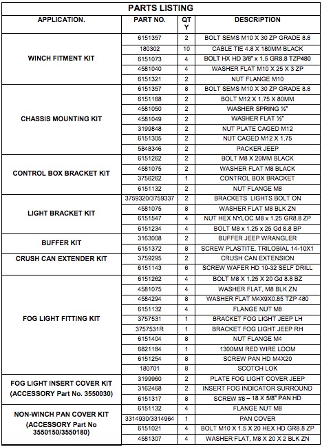
Shop Parts in this Guide
Part Number: 3450230, 3450240, 3450260 & 3450270
Product Description: JEEP WRANGLER JK COMMERCIAL BULL BAR
Suited to vehicle/s: CHRYSLER WRANGLER JK JEEP 2006 ON
WARNING
REGARDING VEHICLES EQUIPPED WITH SRS AIRBAG:
When installed in accordance with these instructions, the front protection bar does not affect operation of the SRS airbag.
ALSO, NOTE THE FOLLOWING:
• This product must be installed exactly as per these instructions using only the hardware supplied.
• In the event of damage to any bull bar component, contact your nearest authorised ARB stocklist. Repairs or modificationsto the impact absorption system must not be attempted.
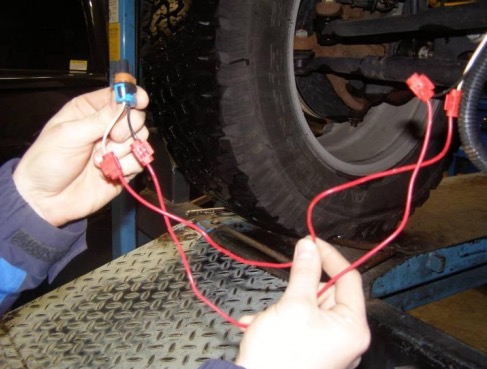
• Do not use this product for any vehicle make or model, other than those specified by ARB.
• Do not remove labels from this bull bar.
• This product or its fixing must not be modified in any way.
• The installation of this product may require the use of specialized tools and/or techniques.
• It is recommended that this product is only installed by trained personnel.
• These instructions are correct as at the publication date. ARB Corporation Ltd. cannot be held responsible for the impact of any changes subsequently made by the vehicle manufacturer.
• During installation, it is the duty of the installer to check correct operation/clearances of all components.
• Work safely at all times.
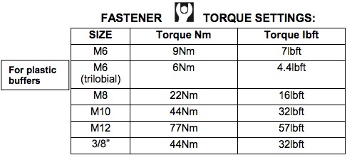
• Unless otherwise instructed, tighten fasteners to specified torque.

GENERAL CARE AND MAINTENANCE
By choosing an ARB Bar, you have bought a product that is one of the most sought after 4WD products in the world. Your bar is a properly engineered, reliable, quality accessory that represents excellent value. To keep your bar in original condition it is important to care and maintain it following these recommendations:
Prior to exposure to the weather your bar should be treated to a Carnauba based polish on all exposed surfaces. It is recommended that this is performed on a six monthly basis or following exposure to salt, mud, sand or other contaminants.
As part of any Pre Trip Preparation, or on an annual basis, it is recommended that a thorough visual inspection of the bar is carried out, making sure that all bolts and other components are torqued to the correct specification. Also check that all wiring sheaths, connectors, and fittings are free of damage. Replace any components as necessary. This service can be performed by your local authorized ARB Stockist.
NOTE: 'WARNING' notes in the fitting procedure relate to OHS situations, where to avoid a potentially hazardous situation it is suggested that protective safety gear be worn or a safe work procedure be employed. If these notes and warnings are not heeded, injury may result.
FITTING PROCEDURE
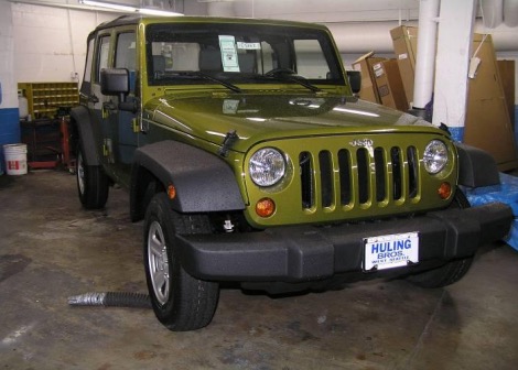
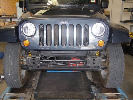
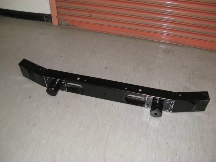
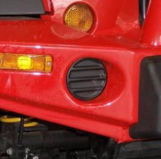
1. Remove plastic bumper from the vehicle including all hardware located behind it.
Note: Vehicle shown in Figure 1a is not fitted with fog lights.
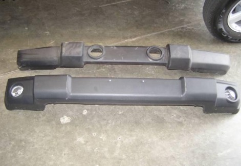
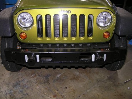
Note: Jeep Wrangler JK comes in three Different versions of bumper bars:
i) No fog lights.
ii) Fog lights positioned inboard.
iii) Fog lights positioned outboard.
Figure 1b shows bumper variants offering fog lights ii) & iii)
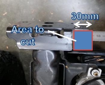
For vehicles not fitted with crush cans, skip step 2 below.
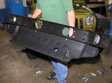
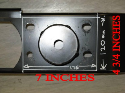
2 a) Once impact beam is removed, mark out a 175x120mm section onto the impact beam on both sides.
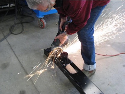
b) Carefully cut marked section using an angle grinder fitted with a turbo disc.
c) Retain crush cans and dispose of the impact beam.
d) Clean up any sharp edges or burs with a file.
e) Apply black spray paint to cut edges to prevent corrosion.
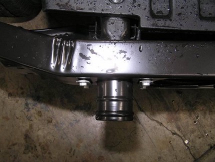
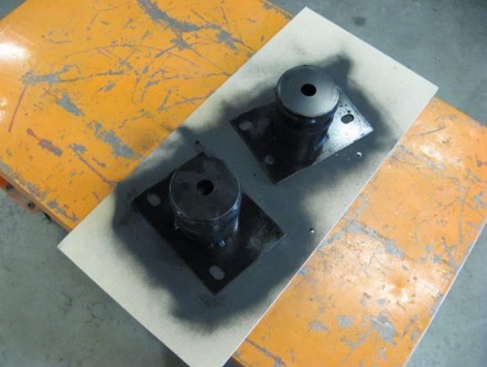
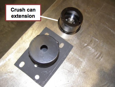
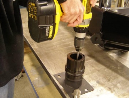
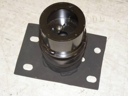
3. Attach crush can extensions supplied with bull bar to crush cans using 6x self-drilling screws supplied with crush can extension fitting kit ACCESSORY Part No 3550140 (3x screws per crush can).
Note: When attaching crush can extensions to crush cans, ensure both parts are concentric to one another.
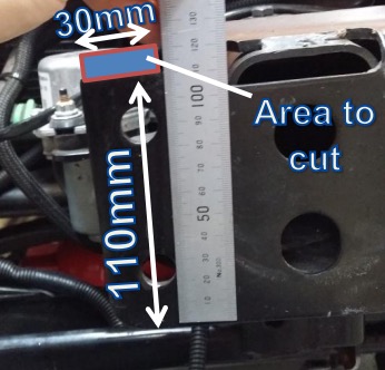
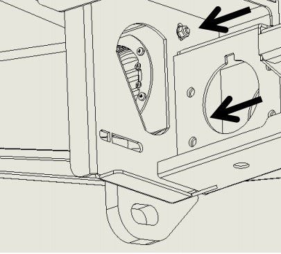
For applications where winch is not going to be fitted, skip step 4 below.
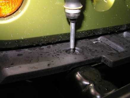
4 a) Mark section on chassis rail front mounting face with reference 110mm from bottom edge (horizontal marking) and 35mm from inside edge (parallel to longitudinal axis of vehicle).
b) Carefully cut marked section using an angle grinder fitted with a turbo disc.
c) Clean up any sharp edges or burs with a file.
d) Apply black spray paint to cut edges to prevent corrosion.
LHS chassis rail shown
For Vehicles not fitted with fog lights, use fog light insert cover kit ACCESSORY Part No. 3550030 in place of fog light for the following installation procedure.
(Refer to Figures on next page)
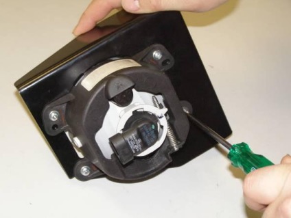
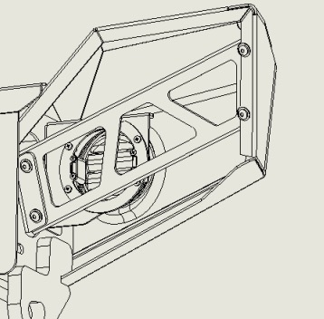
5. Secure fog lights to mounting brackets using M4 fasteners supplied with fog light fitting kit ACCESSORY Part No 6172261.
6. Secure fog light assembly to bull bar using M8 fasteners supplied with fog light fitting kit.
LHS assembly shown
7. Adjust fog light so that it sits central to the fog light aperture in the bull bar. Tighten both bolts on each side of bar to the torque specification on page 2.
Image of fog light fitted to vehicle (from front)
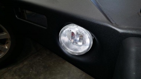
Figure to the left shows what the bull bar should look like once all fog light components are installed correctly.
Note: Final vertical adjustment of the fog light can be carried out using a Torx T20 key once the bull bar is fitted to the vehicle.
LHS Assembly Shown
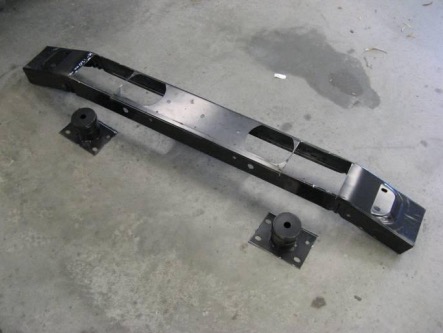
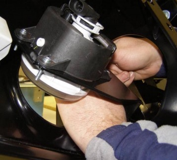
8 a) Position bar on a flat surface upside down so that you have access to both front and rear sections of the bull bar.
b) Fit buffers to the bar by holding each buffer against the front of the bull bar and securing from the rear using 8x 6mm trilobial screws supplied with buffer kit (4 per buffer).
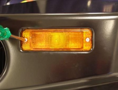
9. To install indicator lights to the bull bar, fit plastic plugs into the cavity in the wing and fix the light to the plastic plug from the front using screws supplied in indicator fitting kit.
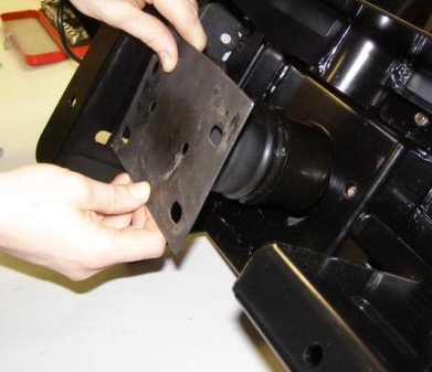
10. Position crush cans into mounting bracket openings located at the rear of the bar.
Note: To hold crush can plate into position as bull bar is offered to the vehicle later on in the installation process, smear a small amount of silicon onto mounting face.
11. Loosely fasten bull bar to vehicle chassis using M10 fasteners supplied in chassis mounting kit.
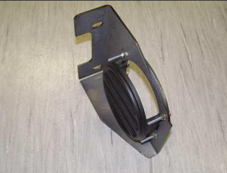
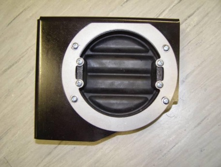
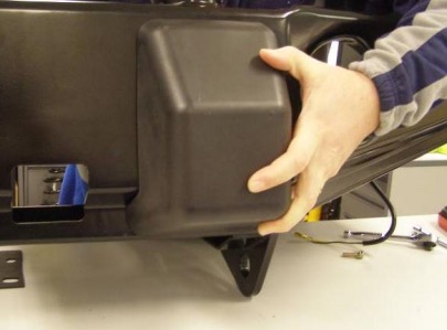
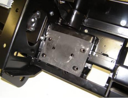
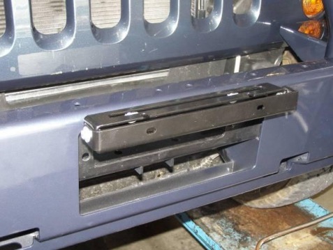
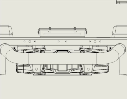
Note: If your vehicle is not going to be fitted with a winch, install pan cover kit ACCESSORY Part No 3550150/3550180 to bull bar before mounting bull bar to vehicle chassis.
(Refer to Figure below)
Pan Cover
For vehicle models 2010 onwards, the following (step 12) is required. For all other models move to step 13.
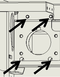
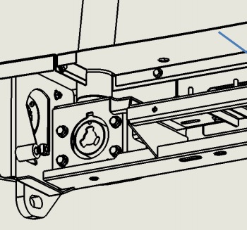
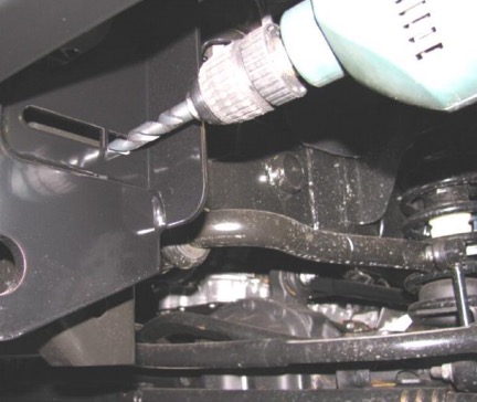
12. Using the bull bar bracket shown in Figure 11 as a guide, carefully drill through the chassis rail side bracket using a 12mm or 1/2 inch drill bit.
Ensure that drill is aligned with rear of the bull bar bracket slot as shown before drilling.
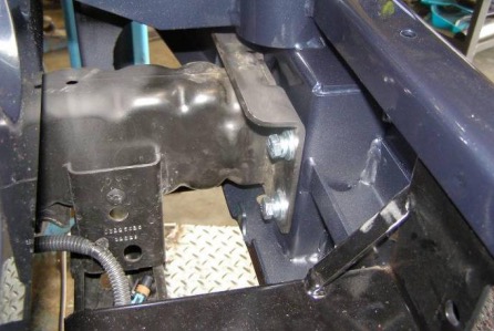
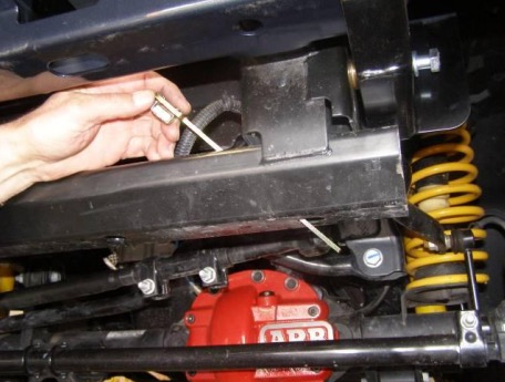
13. Position packers in between bull bar mounting bracket and chassis (at rear most slot in bracket).
Loosely fasten bull bar to chassis sides using M12 fasteners supplied.
Note: Bend tail of captive nut plate to help guide it into chassis rail.
LHS/RHS shown
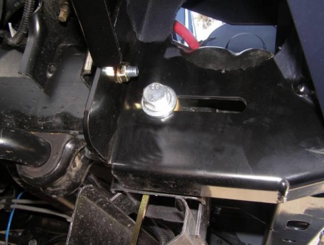
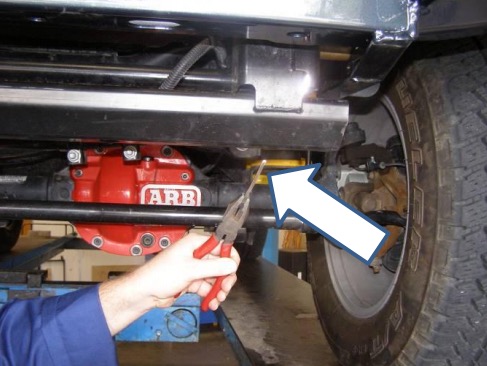
14. Tighten all chassis mounting fasteners to correct torque specifications listed on page 2.
Tighten M10 fasteners first and then proceed to tighten M12 fasteners.
Once all fasteners are torqued, break off nut plate tail protruding below cross member using a pair of pliers.
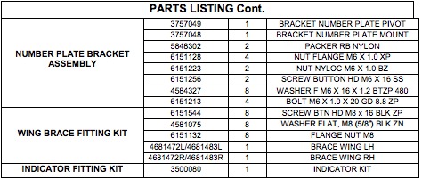
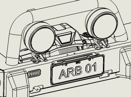
For vehicles not being fitted with a number plate, skip steps 15 & 16.
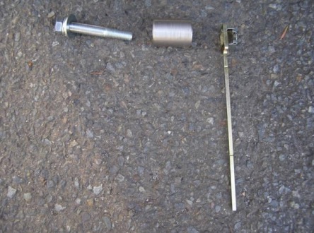
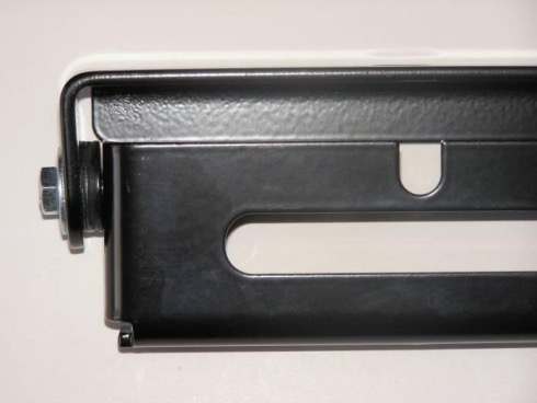
15. Assemble number plate components supplied with number plate fitting kit as per Figure 14.
Ensure assembly is not over tightened so that it may pivot with reasonable amount of friction.
16. Mount number plate bracket assembly to bull bar using M6 fasteners supplied with number plate fitting kit.
FOR ALL WARN WINCHES UP TO XP9.5 INCLUDING ZEON, SMITTYBUILT, MAGNUM AND BUSHRANGER
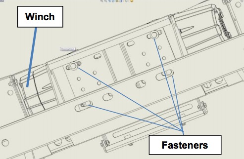
17. Lower winch onto bull bar mounting platform carefully aligning with slots.
Fit 3/8" nuts into winch retaining cavities if applicable.
Loosely fasten winch into position from underneath the vehicle.
Check lateral alignmnet of winch relative to bull bar.
Tighten fasteners to torque specification listed on page 2.
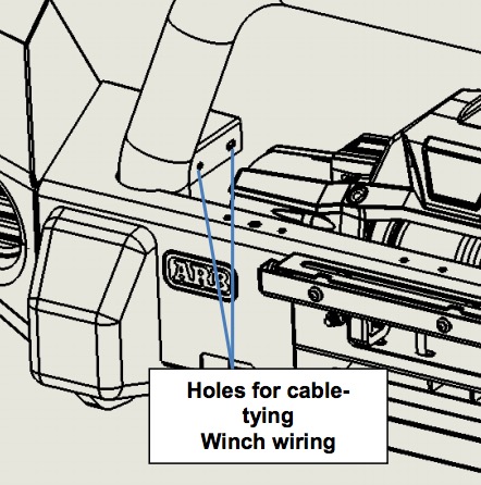
18. Use cable ties to fix winch power cables to pan to tidy up area.
For winch models that come with a control box to be mounted separately to the winch, complete step 19.
19. Fit control box bracket to bar using M8 fasteners supplied with control box bracket using fasteners supplied with winch as per winch supplied fitting instructions.
Note: Use cable ties to keep power cables together and keep clear of all moving components and sharp edges.
If the vehicle is to be fitted with ARB intensity LED driving lights, refer to step 19.
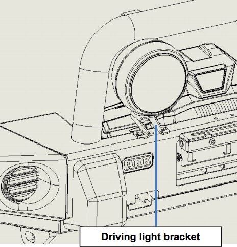
20. Position driving lights onto bull bar aligning holes in bracket with those on top surface of bull bar.
Fasten driving light brackets using M8 fasteners supplied with light bracket kit. A socket extension will be required to fasten M8 nyloc nuts, accessing through the HiLift mount opening.
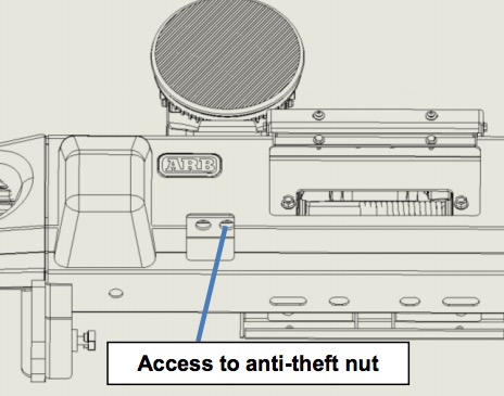
Fasten anti-theft nut and M12 bolt using Intensity pinned socket supplied with ARB Intensity driving light kit.
If the vehicle is to be fitted with IPF driving lights, refer to step 21.
21. Fasten driving light brackets to bull bar using M8 fasteners supplied with light bracket kit.
Fix driving lights to brackets using fasteners supplied with IPF driving light kit.
For vehicles fitted with a winch, refer to step 22.
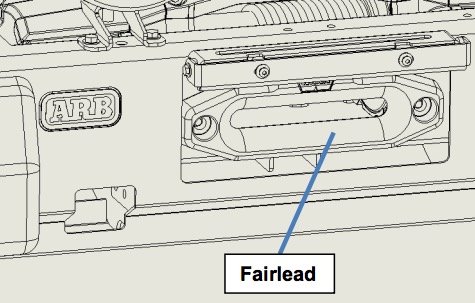
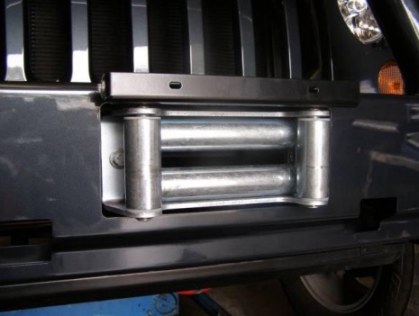
22. Fit the fairlead to the bull bar using M10 fasteners supplied with winch fitment kit.
Roller Fairlead installed
23. Fit wing braces to bull bar using M8 fasteners supplid with wing brace fitting kit.
Tighten fasteners to torque specifications outlined on page 2.
RHS Shown
For vehicles fitted with INBOARD fog lights, complete step 24.
24. Cut 1300mm length of red wire supplied with bolt kit into four equal lengths of 325mm each.
Cut off the fog light plugs from the vehicle loom leaving approximately 100mm of wire on the ends of the plugs.
Using scotch lok fasteners supplied in the bolt kit, fasten the red wire lengths in between plug ends and vehicle loom.
Use cable ties to secure all wiring.
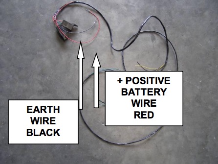
25. For indicator wiring, the loom supplied with the indicator kit is required.
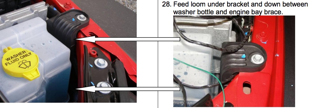
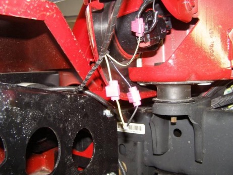
29. a) Feed loom down until LHS indicator spliced wiring is in position to be attached to vehicle indicator.
b) From the bar loom, fit the yellow wire (with black trace) to vehicle indicator loom
white/green (with black trace) securing with a scotch lok.
c) To wire up the bar indicator, scotch lok yellow to yellow wiring and black to black wiring.
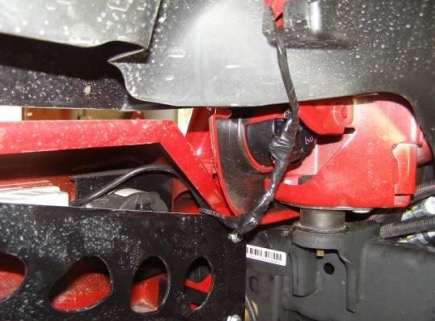
d) After securing wiring, run loom along inside vehicle crossmember to the RHS of vehicle loom using cable ties.
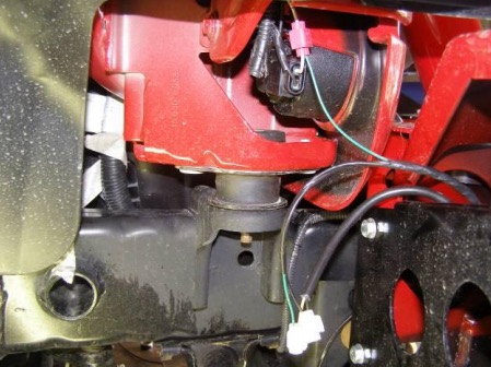
30. a) To wire the indicators to the RHS of vehicle, connect green wire (black trace) from bar loom to white wire (brown trace) from vehicle indicator. Secure using scotch lok.
b) To wire up the bar indicator, scotch lok black to black wiring and green to yellow wiring.
Taped loom LHS shown
31. Bolt number plate to number plate bracket using M6 fasteners supplied with number plate assembly kit.
Torque to specification listed on page 2.
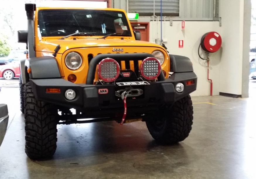
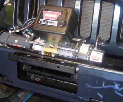
FITTED PRODUCT - Shown with Warn Zeon winch