 FREE 1 to 3-Day Delivery on Orders $149+ Details

How to Install an Air Lift Wireless On Board Air System on your 97-18 Jeep Wrangler TJ, JK & JL
Installation Time
3 hours
Tools Required
- Hoist or floor jacks (1)
- Safety stands (2)
- Safety glasses (1)
- Heavy duty drill (1)
- #2 Phillips bit driver(1)
- 7/32 & 1/4 Drill bits (1)
- 5/16 Driver (1)
- Hose cutter (1)
- Spray bottle with dish soap/water solution (1)
- Digital volt meter (1)

Shop Parts in this Guide
INSTALLATION GUIDE
For maximum effectiveness and safety, please read these instructions completely before proceeding with installation.
Failure to read these instructions can result in an incorrect installation.
Introduction
The purpose of this publication is to assist with the installation, maintenance and troubleshooting of the WirelessONE System.
It is important to read and understand the entire installation guide before beginning installation or performing any maintenance, service or repair. The information here includes a hardware list, step-by-step installation information, safety information and a troubleshooting guide.
Air Lift Company reserves the right to make changes and improvements to its products and publications at any time. Contact Air Lift Company at (800) 248-0892 for the latest version of this manual.
SYSTEM INFORMATION
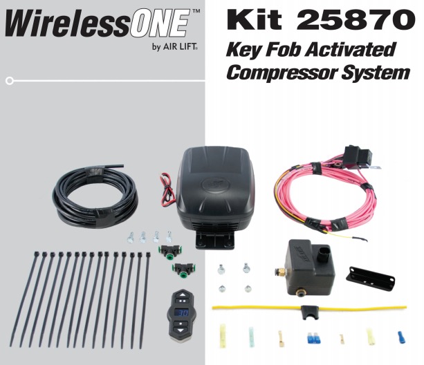
WirelessONE is designed for automatic digital leveling of the on-board compressor system. The kit includes a compressor, manifold, wiring harness, and wireless digital controller. The system can be used in or outside the vehicle, for adjustments in full view of the vehicle.
The wireless digital controller is a compact, battery powered unit. It also includes a clip that can be attached to the vehicle’s visor. Three user-defined memory settings are provided for frequently used settings. As an added safety measure, minimum air pressures are automatically maintained. The manifold is also weather resistant for maximum life expectancy.
IMPORTANT SAFETY NOTICE
The installation of this kit does not alter the Gross Vehicle Weight Rating (GVWR) or payload of the vehicle. Check your vehicle’s owner’s manual and do not exceed the maximum load listed for your vehicle.
Gross Vehicle Weight Rating: The maximum allowable weight of the fully loaded vehicle (including passengers and cargo). This number — along with other weight limits, as well as tire, rim size and inflation pressure data — is shown on the vehicle’s Safety Compliance Certification Label.
Payload: The combined, maximum allowable weight of cargo and passengers that the truck is designed to carry. Payload is GVWR minus the Base Curb Weight.
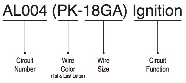
SCHEMATIC CIRCUIT INFORMATION
Example:
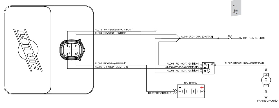
Installation - Electrical Schematic
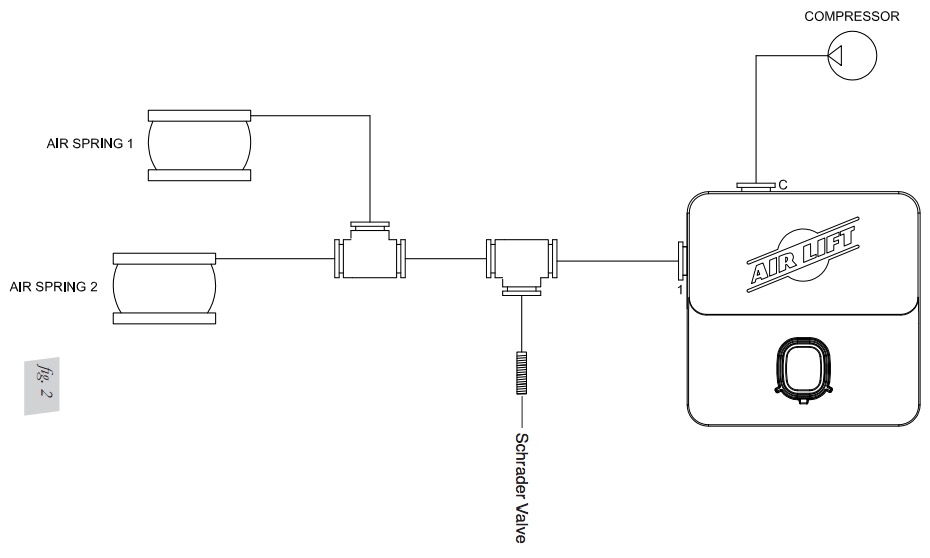
Installation - Pneumatic Schematic
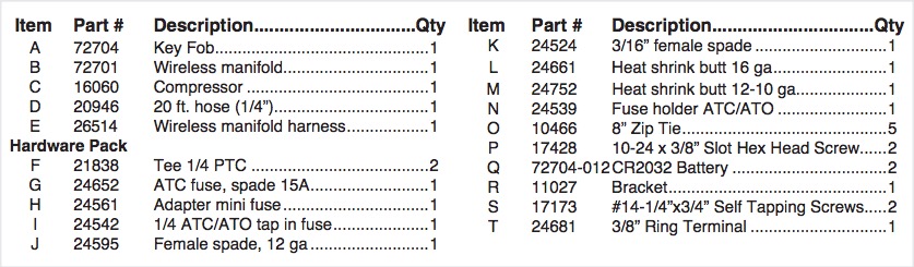
HARDWARE LIST
Installing the WirelessONE System
RECOMMENDED COMPRESSOR LOCATIONS
Important
LOCATE COMPRESSOR IN DRY, PROTECTED AREA ON VEHICLE. DIRECT SPLASH OR EXCESSIVE MOISTURE CAN DAMAGE THE COMPRESSOR AND CAUSE SYSTEM FAILURE.
Disclaimer: If you choose to mount the compressor outside the vehicle please keep in mind the compressor body must be shielded from direct splash and the intake should be snorkeled inside the vehicle. If the compressor does not include a remote mount air filter or if mounting the compressor outside the vehicle, make sure to orient the compressor intake filter so that all moisture can easily drain.
Please also remember...
• To avoid high heat environments
• To avoid mounting the compressor under the hood.
• To check to be sure the compressor harness #2 will reach the compressor and connect to harness #1.
• The compressor can be mounted in any position — vertical, upside down, sideways, etc. (please refer to the instruction manual).
INSTALLING THE COMPRESSOR
1. Select a rigid mounting location for the compressor on the vehicles frame or cross member (fig. 3) that shields the compressor from the elements and heat sources.
NOTE: The electrical harness will force the compressor to be within 24” of the manifold in order to make electrical connections.
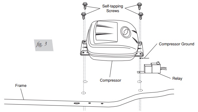
2. Use the supplied self tapping fasteners to fasten the compressor to the frame or cross member.
• One of the self tapping screws will be used as an electrical ground for the compressor ring terminal.
• Another of the self tapping screws can be used to mount the compressor relay
INSTALLING THE MANIFOLD
WARNING: IF THE USER INSTALLS THE MANIFOLD OR COMPRESSOR IN THE CAB OF THE VEHICLE IN EXTREME WEATHER CLIMATES, DO NOT USE ANY ANTI-FREEZE PRODUCT IN THE SYSTEM AS EXHAUST FUMES CAN BE TOXIC. CARE MUST BE TAKEN WHEN USING THIS PRODUCT! IT IS RECOMMENDED THAT THIS PRODUCT’S MSDS SHEET BE REVIEWED BEFORE USE! THIS CAN BE OBTAINED WHERE YOU PURCHASE THIS PRODUCT.
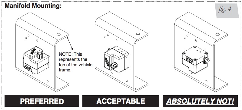
1. Select a rigid mounting location for the manifold on the vehicles frame or cross member that shields the manifold from the elements and heat sources (fig. 4).
2. Use mounting bracket 11027 (R) to secure to the rigid mounting surface with a 17173 fastener (S). The manifold should not be the lowest point in the pneumatic system.
1. Connect electrical connector to manifold (B).
a. Push down till fully seated.
b. Push red secondary lock down.
2. Connect compressor to harness.
a. Cut off terminal on compressor red wire.
b. Strip ¼” insulation off compressor red wire.
c. Crimp on weather proof blue butt splice (L) to compressor red wire.
d. Crimp on weather proof blue butt splice (L) to harness wire pink wire AL007 (PK- 14GA).
e. Heat buttsplice to seal connection.
f. Connect the compressor ground wire ring terminal and the relay to the vehicle ground (fig. 3).
• Using one of the self tapping screws for the compressor you can attach all the components to the vehicle frame ground.
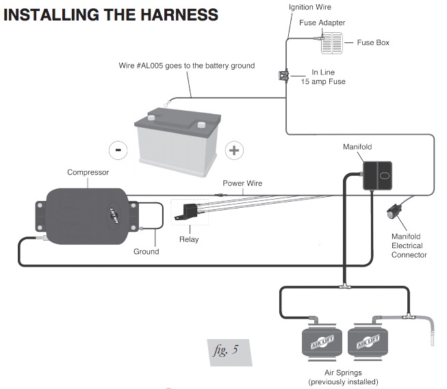
g. Connect the black wire “Ground to Battery” to the negative battery terminal.
3. Connect the AL004 circuit to the vehicle ignition.
a. Route the AL004 (RD-10GA) wire to a 15A ignition source (G).
• Cut off the excess wire length if all is not needed.
b. Strip off ¼’ insulation off both sides of the inline fuse holder (N) and the AL004 (RD-10GA) wire.
c. Crimp on the weather proof yellow butt splice (M) to AL004 (RD-10GA) wire.
d. Crimp on the weather proof yellow butt splice (M) to one side of the inline fuse holder (O).
• Heat buttsplice to seal connection.
e. Select the appropriate type of fuse tap in terminal for your application (fig. 6).
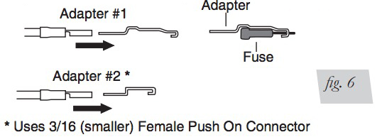
f. Crimp on the correct terminal that mates with the appropriate type of fuse tap in terminal for your application.
g. Connect the terminal to the inline fuse holder (N).
h. Install fuse (G)
ATTACHING THE AIR LINES
Manifold to Compressor:
1. Cut a section of the ¼” DOT air line (D) provided to go from manifold to compressor.
2. Press air line (D) over barb fitting of compressor (C).
3. Insert into “C” port of manifold (B).
Manifold to “T-Fitting”:
1. Cut a section of the ¼” DOT air line (D) provided to go from manifold (B) to “T- Fitting” (F).
2. Press air line (D) into the ”1” fitting of manifold (B).
3. Press other side of air line (D) into “T” fitting (F).
“T-Fitting” to Springs:
1. Cut a section of the ¼” DOT air line (D) provided to go from “T-Fitting” (F) to Left and Right Air Springs.
2. Insert one side of air line (D) into “T-Fitting” (F) and the other into the Air Springs
HOW TO REMOVE AND INSTALL THE BATTERIES IN THE REMOTE CONTROL UNIT
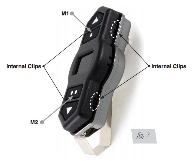
1. To remove the two CR2032 batteries use a small flat screw driver to seperate the two halves of the key fob by prying at the internal clip locations shown in figure 7.
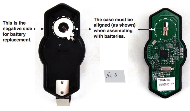
2. Stack the two CR2032 batteries Positive to Negative inside the rear cover.
3. Clip the front cover and circuit board into the rear cover (fig. 8).
OPERATIONAL MODES
Normal Mode: Mode in which the user can increment and decrement the desired pressure, as well as set and recall the three memory pressures. “LB” will be displayed on startup when the battery is getting low.
Settings Mode: Mode in which the user can change the backlighting color, alter the unit of measure (psig, or BAR).
Settings Mode
1. Press and hold the Up and Down buttons for 5 seconds to enter the settings mode.
2. Once in the settings mode the display will display “SE” to indicate settings mode.
3. In the settings mode the M1 button (fig. 7) will scroll through all the backlighting options.
4. The M2 button (fig. 7) will toggle between the unit of measure for the pressure and display “PS” for psig and “BA” for BAR.
5. Pressing the UP and Down buttons together will exit back into the Normal Mode.
Normal Mode
Increasing desired pressure:
1. Initial press of any button will wake up display and not perform any function.
2. Upon wake up the LCD will display the Desired pressure.
3. Pressing the up arrow will increment the desired pressure by 1 psig, or 0.1BAR depending on the unit of measure selected.
• When the user releases the button the new desired pressure will be transmitted to the receiver.
4. Holding the up arrow will increment the desired pressure in units of 5psig or 0.5BAR depending on the unit of measure selected.
• When the user releases the button the new desired pressure will be transmitted to the receiver.
5. The Maximum pressure will be 120psig or 8.3 BAR.
• If desired pressure is max pressure then pressing the Up arrow will result in no function.
Decreasing desired pressure:
1. Initial press of any button will wake up display and not perform any function.
2. Upon wake up the LCD will display the Desired pressure.
3. Pressing the down arrow will decrease the desired pressure by 1 psig, or 0.1BAR depending on the unit of measure selected.
• When the user releases the button the new desired pressure will be transmitted to the receiver.
4. Holding the down arrow will decrease the desired pressure in units of 5psig or 0.5BAR depending on the unit of measure selected.
• When the user releases the button the new desired pressure will be transmitted to the receiver.
5. The Minimum pressure will be 0psig or 0 BAR.
• If desired pressure is min pressure then pressing the Down arrow will result in no function.
Saving and Recalling Memory 1:
Recalling Memory
• Initial press of any button will wake up display and not perform any function.
• Upon wake up the LCD will display the Desired pressure.
• Press the M1 button to set the M1 pressure as the desired pressure.
• Upon the press of the M1 button the display will display “M1”.
• Once the button is released the display will display the new desired pressure and transmit the desired pressure to the receiver.
Saving to Memory
• With the desired pressure on the LCD Press and hold the memory button for 5 seconds to set the desired pressure to memory 1.
• While the M1 button is pressed the display will display “M1”.
• Once the desired pressure is saved to M1 the display will flash the backlight three times.
Saving and Recalling Memory 2:
Recalling Memory
• Initial press of any button will wake up display and not perform any function. • Upon wake up the LCD will display the Desired pressure.
• Press the M2 button to set the M2 pressure as the desired pressure.
• Upon the press of the M2 button the display will display “M2”.
• Once the button is released the display will display the new desired pressure and transmit the desired pressure to the receiver.
Saving to Memory
• Press and hold the memory button for 5 seconds to set the desired pressure to memory 2.
• While the M2 button is pressed the display will display “M2”.
• Once the desired pressure is saved to M2 the display will flash the backlight three times.
Saving and Recalling Memory 3:
Recalling Memory
• Initial press of any button will wake up display and not perform any function.
• Upon wake up the LCD will display the Desired pressure.
• Press the M1 & M2 buttons to set the M3 pressure as the desired pressure. • Upon the press of the M1 & M2 buttons the display will display “M3”.
• Once the buttons are released the display will display the new desired pressure
Saving to Memory
• Press and hold M1 & M2 buttons for 5 seconds to set the desired pressure to memory 3.
• While the M1 & M2 buttons is pressed the display will display “M3”.
• Once the desired pressure is saved to M3 the display will flash the backlight three times.
HOW TO SYNC THE RECEIVER TO THE TRANSMITTER (ONLY NEEDED WITH A REPLACEMENT TRANSMITTER)
1. Turn ignition on.
2. Locate the sync wire in the wire harness.
• It will be the yellow wire that is looped with a yellow cap around it.
3. Remove the yellow wire from the cap leaving the cap attached to the harness.
4. Disconnect power to the receiver.
• Unplug the connector on the top.
5. Connect power to the receiver while grounding the sync input.
6. Listen for 3 clicks of the internal solenoid, then one click every second.
• This will indicate that you are now in the “sync mode”.
• Sync mode will last for 30 seconds total.
• Within the 30 seconds press any button on the transmitter to send a message to the receiver.
• Once the receiver has received a message it will sync with that transmitter and stop clicking the solenoid in 1 second intervals.
7. Re-insert the yellow wire terminal into the molded cap.
CHECKING THE SYSTEM
1. Pressurize the system to check for leaks.
2. Inspect all air line connections with a solution of 1/5 dish soap to 4/5 water. If a leak is detected in a push-lock-fitting, cut the hose end square and reinstall the air line to the fitting. Make sure the air line is cut off squarely and that the air line is completely pushed into the fitting.
3. If the compressor or the solenoid fails to function, check the 15 AMP fuse and ground connection. Repair and replace as necessary.
FCC INFORMATION TO USER
THIS DEVICE COMPLIES WITH PART 15 OF THE FCC RULES. OPERATION IS SUBJECT TO THE FOLLOWING TWO CONDITIONS: (1) THIS DEVICE MAY NOT CAUSE HARMFUL INTERFERENCE, AND (2) THIS DEVICE MUST ACCEPT ANY INTERFERENCE RECEIVED, INCLUDING INTERFERENCE THAT MAY CAUSE UNDESIRED OPERATION.
NOTE: THE MANUFACTURER IS NOT RESPONSIBLE FOR ANY RADIO OR TV INTERFERENCE CAUSED BY UNAUTHORIZED MODIFICATIONS TO THIS EQUIPMENT. SUCH MODIFICATIONS COULD VOID THE USER’S AUTHORITY TO OPERATE THIS EQUIPMENT.
FCC ID: YHT-BRM920AJM1017
Warranty and Returns Policy
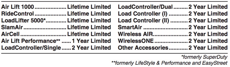
Air Lift Company warrants its products, for the time periods listed below, to the original retail purchaser against manufacturing defects when used on catalog-listed applications on cars, vans, light trucks and motorhomes under normal operating conditions for as long as Air Lift manufactures the product. The warranty does not apply to products that have been improperly applied, improperly installed, used in racing or off-road applications, used for commercial purposes, or which have not been maintained in accordance with installation instructions furnished with all products. The consumer will be responsible for removing (labor charges) the defective product from the vehicle and returning it, transportation costs prepaid, to the dealer from which it was purchased or to Air Lift Company for verification. Air Lift will repair or replace, at its option, defective products or components. A minimum $10.00 shipping and handling charge will apply to all warranty claims. Before returning any defective product, you must call Air Lift at (800) 248-0892 in the U.S. and Canada (elsewhere, (517) 322-2144) for a Returned Materials Authorization (RMA) number. Returns to Air Lift can be sent to: Air Lift Company • 2727 Snow Road • Lansing, MI • 48917.
Product failures resulting from abnormal use or misuse are excluded from this warranty. The loss of use of the product, loss of time, inconvenience, commercial loss or consequential damages is not covered. The consumer is responsible for installation/reinstallation (labor charges) of the product. Air Lift Company reserves the right to change the design of any product without assuming any obligation to modify any product previously manufactured.
This warranty gives you specific legal rights and you may also have other rights that vary from state-to-state. Some states do not allow limitations on how long an implied warranty lasts or allow the exclusion or limitation of incidental or consequential damages. The above limitation or exclusion may not apply to you. There are no warranties, expressed or implied including any implied warranties of merchantability and fitness, which extend beyond this warranty period. There are no warranties that extend beyond the description on the face hereof. Seller disclaims the implied warranty of merchantability. (Dated proof of purchase required.)
Replacement Information
If you need replacement parts, contact the local dealer or call Air Lift customer service at (800) 248-0892. Most parts are immediately available and can be shipped the same day.
Contact Air Lift Company customer service at (800) 248-0892 first if:
• Parts are missing from the kit.
• Need technical assistance on installation or operation.
• Broken or defective parts in the kit.
• Wrong parts in the kit.
• Have a warranty claim or question.
Contact the retailer where the kit was purchased:
• If it is necessary to return or exchange the kit for any reason.
• If there is a problem with shipping if shipped from the retailer.
• If there is a problem with the price.
Contact Information
If you have any questions, comments or need technical assistance contact our customer service department by calling (800) 248-0892, Monday through Friday. For calls from outside the USA or Canada, our local number is (517) 322-2144.
For inquiries by mail, our address is PO Box 80167, Lansing, MI 48908-0167. Our shipping address for returns is 2727 Snow Road, Lansing, MI 48917.
You may also contact us anytime by e-mail at [email protected] or on the web at www.airliftcompany.com.
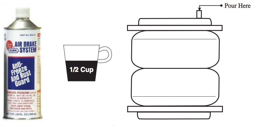
Important
To avoid COLD WEATHER FREEZE UP:
Add 4 oz. (1/2 cup) of
“GUNK” Brand AIR BRAKE ANTI FREEZE
Directly into each flex member. Remove the air line and/or fitting from the air bag and fill directly. Gunk Brand Air Brake Anti-Freeze may be purchased at an automotive parts store or truck supply store.
WARNING: IF THE USER INSTALLS THE MANIFOLD OR COMPRESSOR IN THE CAB OF THE VEHICLE IN EXTREME WEATHER CLIMATES, DO NOT USE ANY ANTI-FREEZE PRODUCT IN THE SYSTEM AS EXHAUST FUMES CAN BE TOXIC. CARE MUST BE TAKEN WHEN USING THIS PRODUCT! IT IS RECOMMENDED THAT THIS PRODUCT’S MSDS SHEET BE REVIEWED BEFORE USE! THIS CAN BE OBTAINED WHERE YOU PURCHASE THIS PRODUCT.
WARNING: DO NOT FILL THROUGH COMPRESSOR OR MANIFOLD — DAMAGE WILL OCCUR.
CAUTION: DO NOT USE ENGINE ANTI-FREEZE
Check fluid levels in flex member every year (add if needed).
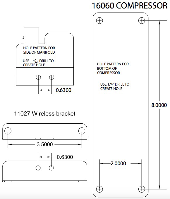
Templates
Need Help?
Contact our customer service department by calling (800) 248-0892, Monday through Friday. For calls from outside the USA or Canada, our local number is (517) 322-2144.
Register your warranty online at www.airliftcompany.com/warranty
