 FREE 1 to 3-Day Delivery on Orders $149+ Details

How to Install AFE Momentum GT Pro 5R Stage-2 Intake System - Middle East Edition on your Wrangler
Installation Time
1 hours
Tools Required
- 8mm, 10mm and 7/16" nut driver
- 1/4" driver
- 10mm deep socket

Shop Parts in this Guide
Instruction Manual
• Please read the entire instruction manual before proceeding.
• Ensure all components listed are present.
• If you are missing any of the components, call customer support at 951-493-7100.
• Ensure you have all necessary tools before proceeding.
• Do not attempt to work on your vehicle when the engine is hot.
• Disconnect the negative battery terminal before proceeding.
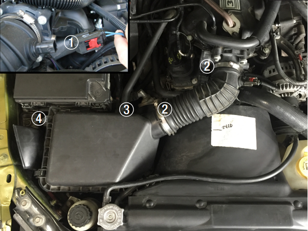
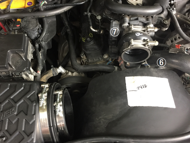
Refer to Figure A for Steps 1-6
Step 1: Disconnect the temp sensor wire. Slide the red tab back then push down on the release lever (Be careful not to break the connector) 1 .
Step 2: Loosen the clamp at the throttle body and air filter housing using an 8mm nut driver or socket. Remove the OE intake tube 2 .
Step 3: Disconnect the Crank Case Vent (CCV) hose at the back of the OE air box 3 .
Step 4: To remove the OE air box, pull the box straight up. Leave OE rubber grommets in place.
Step 5: Remove the M6 bolt that secures the intake housing mounting bracket to the inner fender well (Save the bolt as it will be reused) 4 .
Step 6: Carefully, remove the temp sensor from the OE intake tube by pulling and twisting straight out (Do not bend from side to side while removing the sensor).
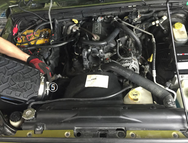
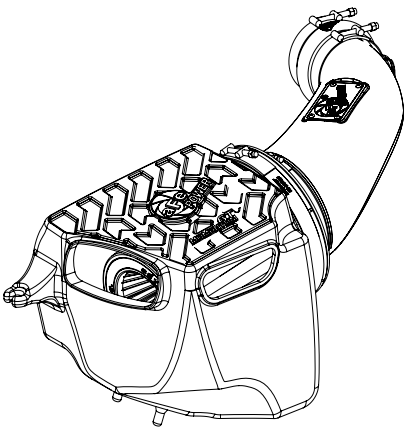
Refer to Figure B for Steps 7-9
Step 7: Slip the larger T-bolt clamp (03-50352) onto the aFe housing but do not tighten yet.
Step 8: Insert the Momentum filter into the housing and tighten T-Bolt clamp using your 10mm deep socket 5 .
Step 9: Insert the housing assembly into the vehicle as shown and guide the lower housing pins into the OE rubber grommets.
Refer to Figure C for Steps 10-11
Step 10: Slip both clamps over the coupling as shown and slip over throttle body 6.
Step 11: Tighten the clamp over the throttle body only at this time 7 .
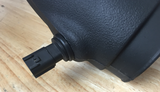
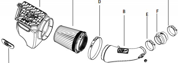
Refer to Figure D for Steps 12-13
Step 12: Insert the provided rubber grommet into the new aFe intake tube.
Step 13: Holding the rubber grommet from the inside, twist and insert the temp sensor into the grommet. Do not bend from side to side when installing the sensor. Using a little lubricant on the inside of the rubber grommet may be helpful when performing this.
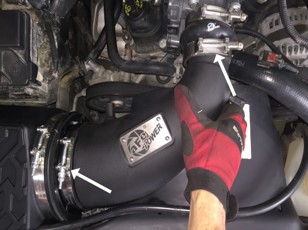
Refer to Figure E for Step 14
Step 14: Insert the aFe tube into the filter as shown. Next rotate the other end of the tube lining it up with the throttle body and insert into the coupling you have previously installed.
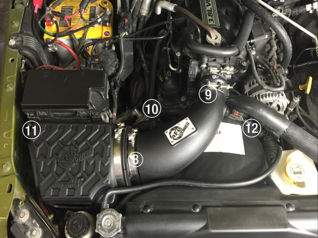
Refer to Figure F for Steps 15-20
Step 15: Tighten medium T-Bolt clamp securing the tube to the filter 8 .
Step 16: Tighten small T-bolt clamp over coupling 9 .
Step 17: Reinstall CCV hose in location shown 10 .
Step 18: Install the M6 bolt you removed in step 5 through the mounting tab on the housing at this time 11 .
Step 19: Reconnect the temperature sensor wiring harness, then slide the red clip forward 12 .
Step 20: Re-check all your work.
*Verify all connections are secure 100-200 miles after installation.

