 FREE 1 to 3-Day Delivery on Orders $149+ Details

How to Install AFE Magnum FORCE Stage-2 Pro 5R Cold Air Intake System on your Jeep Wrangler

Shop Parts in this Guide
Instruction Manual
• Please read the entire instruction manual before proceeding.
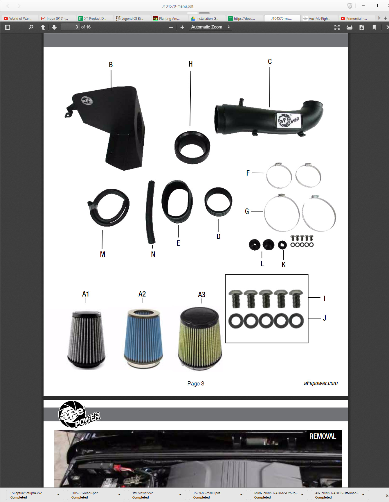
• Ensure all components listed are present.
• If you are missing any of the components, call customer support at 951-493-7100.
• Ensure you have all necessary tools before proceeding.
• Do not attempt to work on your vehicle when the engine is hot.
• Disconnect the negative battery terminal before proceeding.
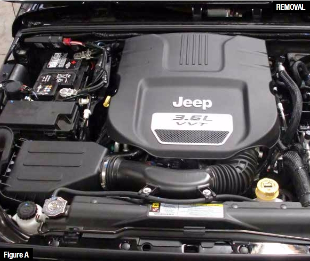
Refer to Figure A for Step 1
Step 1: Remove the engine cover.
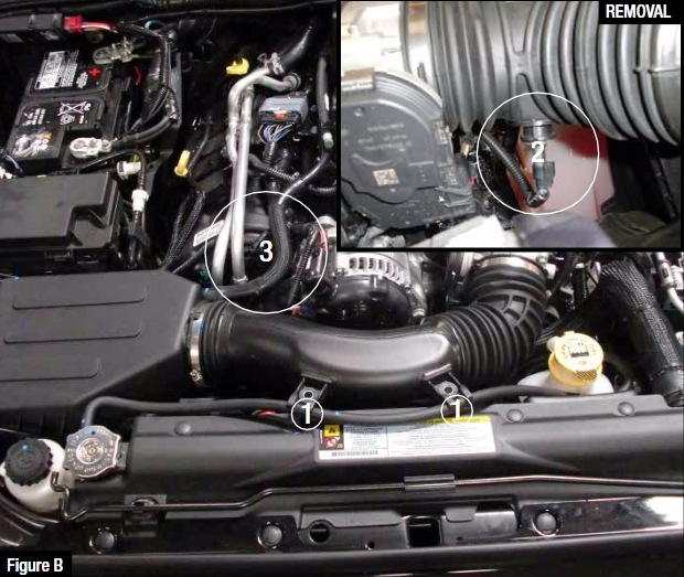
Refer to Figure B for Steps 2-6
Step 2: Remove the two 10mm bolts from the intake tube. 1
Step 3: Disconnect the temp sensor wire harness. 2
Step 4: Loosen the hose clamp at the throttle body.
Step 5: Completely remove the small section of crankcase vent (CCV) hose. It should be pulled off of the air filter housing and the tube to the engine. 3
Step 6: Remove the stock intake tube, and air filter housing by pulling straight up and out of the vehicle.
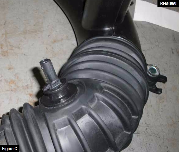
Refer to Figure C for Step 7
Step 7: Twist the temp sensor about 45 degrees counter-clockwise and pull it straight up to remove from stock tube.
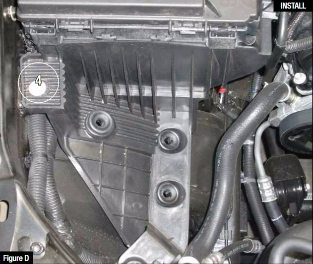
Refer to Figure D for Step 8
Step 8: Remove the 10mm bolt that secures the plastic tray onto the inner fender, but do not remove the plastic tray.
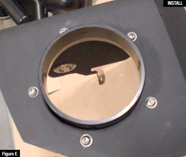
Refer to Figure E for Step 9
Step 9: Install the air filter adaptor in the housing and secure using the 5 washers and 5 screws provided.

Refer to Figure F for Steps 10-12
Step 10: Install the trim seal on the housing.
Step 11: Install the two spacers on the pegs located on the bottom of the housing. 5
Step 12: Install the assembled housing into the vehicle as shown. Secure the housing using the OE bolt removed from Step 8.
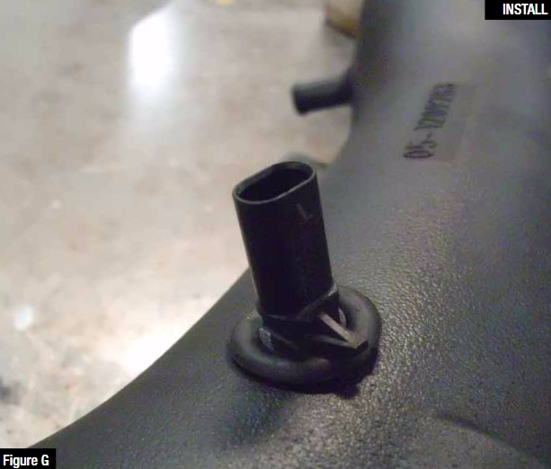
Refer to Figure G for Steps 13-14
Step 13: Insert the provided grommet into the new aFe intake tube.
Step 14: Insert the OE temp sensor into the grommet.
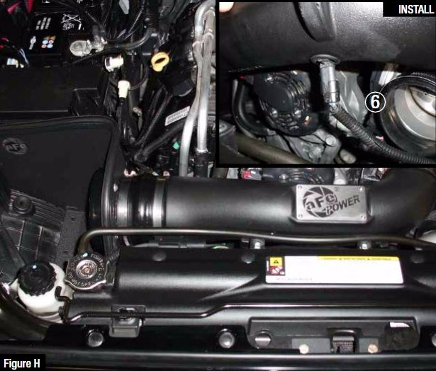
Refer to Figure H for Steps 15-19
Step 15: Install the provided couplings and clamps onto the vehicle. The straight coupling (05-00419) goes on the throttle body. The hump coupling (05-00794) goes on the air filter adaptor.
Step 16: Install the intake tube as shown. Align the tube so that the coolant return line runs above the fan shroud.
Step 17: Plug in the temp sensor harness. 6
Step 18: Install the new CCV hose. (Note: Use lubricant on the outside of the OE tube)
Step 19: Snap the coolant line into the clips on the front of the aFe intake tube.
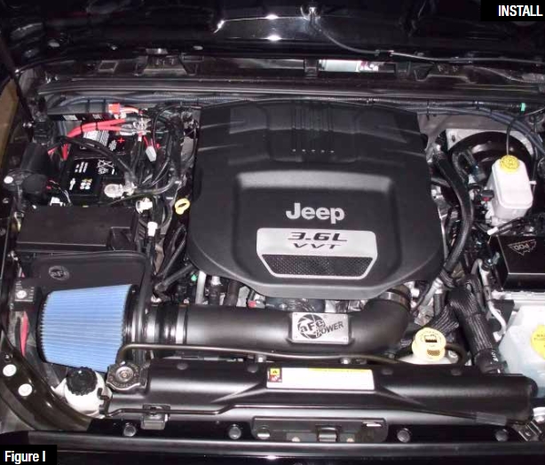
Refer to Figure I for Steps 20-23
Step 20: Install the aFe high performance air filter.
Step 21: Tighten all clamps.
Step 22: Reinstall the engine cover
Step 23: Your installation is now complete
NOTE: Retighten all connections after approximately 100-200 miles.
Place the included CARB EO sticker on or near the device on a smooth, clean
surface. EO identification label is required to pass the smog inspection.
