FREE 1 to 3-Day Delivery on Orders $149+ Details

How to Install AFE 1-1/2 in. Twisted Steel Header & Connection Pipe - Race Series (00-06 4.0L Wrangler TJ) on your Jeep Wrangler
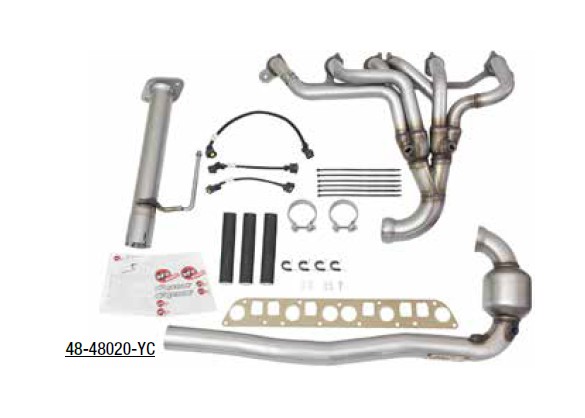
48-48020-YC
• P/N 05-144122: Header (x1)
• P/N 05-144124: Extension Pipe (x1)
• P/N 05-144123: Converter Pipe w/cat (x1)
• P/N 05-01182: Gasket
• P/N 05-41284: Ball Joint, Clamp (x1)
• P/N 05-41061: 2-1/2"SS Band Clamp (x1)
• P/N 05-46123: Fire Sleeve 24"
• P/N 05-60167: Zip Ties (x6)
• P/N 05-46168: 27" 02 Extension (x1)
• P/N 05-46145: 9" 02 Extension (x2)
• P/N 03-50044: Nut, 1/4" (x4)
• P/N 03-50062: Washer 1/4" (x4)
• P/N 03-50100: Screw 1/4" (x1)
• P/N 03-50377: Clamp Fixing (x4)
48-48020-YN
• P/N 05-144122: Header (x1)
• P/N 05-144124: Extension Pipe (x1)
• P/N 05-144135: Converter Pipe w/o Cat (x1)
• P/N 05-01182: Gasket
• P/N 05-41284: Ball Joint, Clamp (x1)
• P/N 05-41061: 2-1/2" SS Band Clamp (x1)
• P/N 05-60167: Zip Ties (x6)
• P/N 05-46145: 9" 02 Extension (x1)
CAUTION: Allow time for your vehicle to cool down prior to installation. When working on or under your vehicle proceed with caution. Exhaust systems reach high temperatures and may cause serious burns. Wear protective safety equipment; eye goggles and gloves to ensure a safe installation. aFe recommends professional installation on our products.
Step 1: (Read Instructions prior to installation) Secure vehicle on jack stands (Refer to your manual for specified jack stands positions).
Step 2: Disconnect the battery before starting work on the exhaust system.
Step 3: Remove the intake air hose off the stock air intake pipe.
Step 4: Remove the two hose clamps securing the stock air intake pipe to the stock air box and throttle body. remove stock air intake pipe.
Step 5: On the intake manifold assembly, remove the throttle cables.
Step 6: Disconnect any electrical connectors and vacuum lines on the intake manifold and throttle body. Be sure to label the lines to ensure correct installment.
Step 7: Remove the fuel injector harness from the cylinder head.
Step 8: Disconnect vacuum harness and vacuum brake booster from the intake manifold under the intake manifold.
Step 9: Remove the fuel line from the fuel rail.
Step 10: Before initiating this step, ensure that you have a diagram of the routing of the serpentine belt. Now, carefully remove the serpentine belt by taking load off the belt tensioner pulley (rotate in a downward and clockwise direction) and slide the serpentine belt off one of the pulleys.
Step 11: Remove the three bolts securing the power steering pump to the intake manifold and move the pump out of the way but DO NOT disconnects the lines.
Step 12: From under the vehicle, disconnect the two after cat oxygen sensors from the wire harness.
Step 13: Now remove the three nuts securing the catalytic converter down pipe to the exhaust system.
Step 14: Remove the (x4) bolts securing the catalytic converters to the stock exhaust manifold. Remove down pipe. Be careful when initiating this step, removing the four bolts will cause the catalytic converters to fall so it is a good idea to have the help of a second hand when removing this down pipe, remove the (x2) bolts & nuts from the exhaust system & remove the rear catalytic converter.
Step 15: Using an engine hoist, suspend the engine from the engine bay to prevent from dropping down as the left side motor mount will be removed.
Step 16: From under the vehicle, remove the three bolts securing the left side motor mount bracket to the engine block.
Step 17: Now remove the nut and bolt securing the left side motor mount bracket to the motor mount. Remove motor mount bracket.
Step 18: Remove the nut and bolt securing the left side motor mount to the chassis. Remove motor mount. (Note: The bolt can either be accessed from under the vehicle or from under the hood.)
Step 19: Disconnect the front and rear oxygen sensors at the wire harness.
Step 20: From under the vehicle, remove the four bolts and washers securing the stock exhaust and intake manifold to the engine.
Step 20: Remove one nut (to the rear of the vehicle) securing the stock exhaust manifold to the engine.
Step 22: Using the same engine hoist, suspend the intake manifold to prevent from dropping down. The intake manifold shares the same bolts and washers with the exhaust manifold so this step is important.
Step 23: From under the hood, remove one nut (located at the front of the vehicle) securing the stock exhaust manifold to the engine.
Step 24: Now remove the five bolts and washers securing the stock exhaust and intake manifold to the engine.
Step 25: Now remove the intake manifold off the pins by wiggling out and away from the engine and suspend slightly up.
Step 26: From under the vehicle, carefully remove the stock exhaust manifold off the engine studs and remove.
Step 27: Now remove the intake/exhaust manifold gasket.
Step 28: Before removing the oxygen sensors, note which the front oxygen sensor is and which is the rear oxygen sensor. A permanent marker is recommended.
Step 29: On a workbench, carefully remove the front oxygen sensor off the stock exhaust manifold and install onto the front O2 bung on the AFE Header.
Step 30: Now remove the rear oxygen sensor from the stock exhaust manifold and install onto the rear O2 bung on the AFE Header.
Step 31: Ensuring that the cylinder head is free from any dirt and/or debris, install the supplied AFE Gasket. From top of the vehicle put the aFe Header onto the cylinder head studs using the two original nuts but do not tighten.
Step 32: Ensuring that the intake manifold is free from any dirt and/or debris, align the intake manifold and slide onto the pins on the cylinder head and secure using the four original bolts and washers but do not tighten.
Step 33: From under the hood, install the five bolts and washers do not tighten.
Step 34: Tighten the nine bolts and nuts starting with the middle and working your way out.
Step 34: Install the aFe extension pipe to the cat back using the provided 2 bolts & nuts.
Step 36: Install the aFe converter pipe to the header and extension pipe using the ball joint clamp and the 2 ½ band clamp, align system and tighten.
Step 37: Install all oxygen sensors
Step 38: Plug in the upper oxygen sensor plugs closer to the intake manifold first. Start with the front oxygen sensor plug to the header using the supplied 9” extension link. The rear header oxygen sensor plug wire does not need an extension.
Step 39: Now remove the remaining oxygen sensor plugs from the stock catalytic converters. Remove one at a time avoid confusion. (Note: 2004-2006 models requires zip-ties to hold 02 extension leads)
Step 40: Slip the 8” heat resistant sleeve over the 27” extension link provided; also slip an 8” heat resistant sleeve over the stock OE sensor plug wire. Then plug the extension link into the rear oxygen sensor plug and run it in between the header collector and the oil pan. Use the clamp fittings and nuts & washers provided in the kit and tighten up the clamp fittings on the stock bolts from the oil pan. With supplied must you must use 3 clamp fittings on the oil pan to avoid the extension link from rubbing on the header collector.
Step 41: Follow the same steps as line #40 for the front oxygen sensor plug. The only difference is you will use a 9” extension link with the 8” heat resistant sleeve. Plug in the 9” extension link into the oxygen sensor and the stock wire harness plug. Make sure to use a clamp fitting and bolt it onto the stock bracket from the oil pan using the ¼”-20 x ¾” bolt and nut provided. To keep the extension connector away from the catalytic converter and causing any damage.
Step 42: Install the motor mount using the original nut and bolt tighten.
Step 43: Now install the motor mount bracket to the motor mount using the original nut and bolt and tighten.
Step 44: Using the engine hoist to align the motor mount bracket, install the three original bolts and tighten.
Step 45: Re-install power steering pump using the three original bolts.
Step 46: Re- install the belt and adjust the belt tensioner to the vehicle specification.
Step 47: Re-install the fuel injector harness to the cylinder head.
Step 48: Re-install the throttle body cables & fuel line rail.
Step 49: Re-install the stock air intake tube removed two original hose clamps and tighten.
Step 50: Install the intake air hose.
Step 51: RE-CHECK ALL YOUR WORK!
Step 52: Your installation is now complete. It is recommended to re-tighten all exhaust component after 50-100 miles.