FREE 1 to 3-Day Delivery on Orders $149+ Details

How to Install ZRoadz Modular Roof LED Light Bar Multi-Mount on your 87-18 Jeep Wrangler YJ, TJ, JK & JL
Tools Required
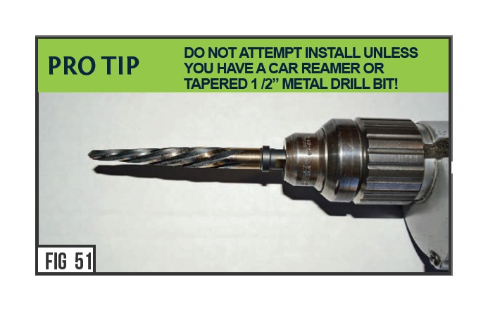
- Tapered 1 /2” drill bit or car reamer
- Drill
- Air Hose & Nozzle
- Alcohol Cleaning Solution
- Cleaning Rag
- Socket Set & Ratchet Tool
- Ratchet Extensions
- Various Wrenches
- Dikes or Snips
- Torx Bits & Allen Set
- Heat Gun

Shop Parts in this Guide
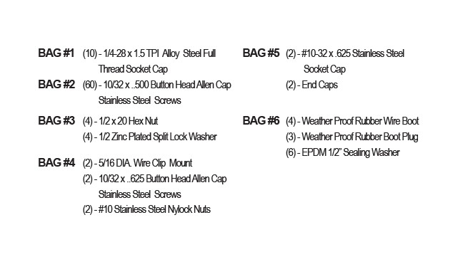
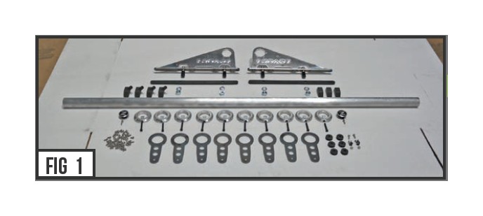
Parts included
Materials needed
- Clear RTV Silicone
- 1/2” x 1/4” DIA Shrink Tube
Hardware included
START HERE
PLEASE READ AND UNDERSTAND ALL INSTRUCTIONS BEFORE INSTALLATION. Auto makers offer varied models to each vehicle and occasionally manufacture more than one body style of the same model. To assure your part is correct; our tech department can be contacted at [email protected] to verify fitment and assist with technical questions. All other inquires can be directed to [email protected]. In the event you do not have internet access please call 844-653-8040
BEFORE YOU BEGIN [LED LIGHT BRACKET INSTALLATION]
Before you begin the installation you must first confirm the barle ngth you purchased and your vehicle roof channel width from the far right edge and fa rleft edge is within the minimum specification for installation. It is also important to note that the minimum roof channel widht at its narrowest point must be greater than ¾”. If your vehicle does not meet these minimum requirements this product will not install properly and should be returned to your ZROADZ authorized distributor.
1) It is now time to begin assembly of the Upright Mounts.
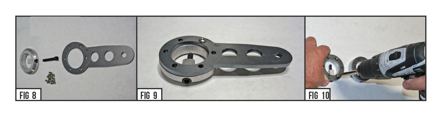
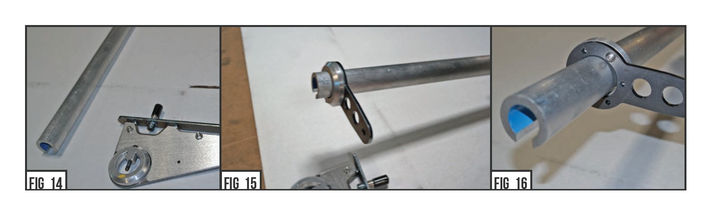
2) Start with screwing the Steel Socket Caps (From Bag #1) into the Bracket Couplers as seen in Figure #3. There should be 10 units. DO NOT BOTTOM OUT as you will need it adjustable.
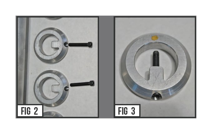
3) Now fix a Bracket Coupler to the inside of the Upright Mounts using the Button Head Allen Cap Screws (From Bag #2). Make certain the Coupler is clocked as seen in Figures #4 & #6.
Repeat for the opposite side Upright Mount.
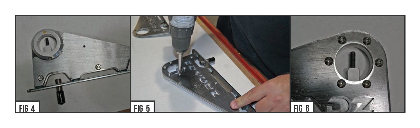
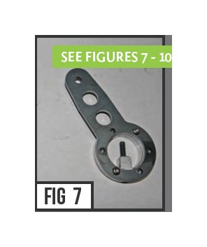
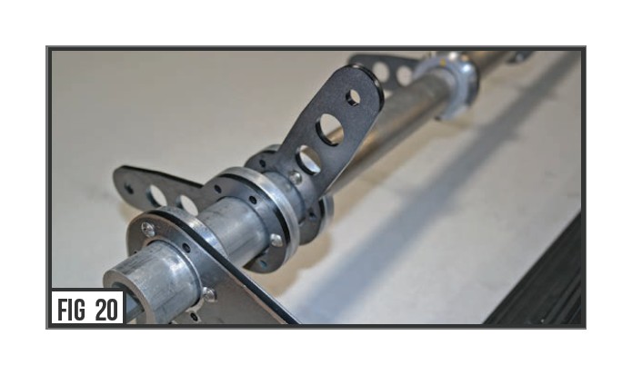
4) At this time, go ahead and assemble at least 2 - 4 (or more) of the Bracket Assemblies. Some will be clocked straight with the Coupler Set Screw pointed to 12:00 o’clock, (Fig. #9) while some should be offset with the Set Screw pointed to 3:00 o’clock (Fig. #7).
5) Before you determine your light configuration you must determine the size and quantity of lights you plan to install. First measure the roof from the inside edge of the roof channel on the Driver Side, to the inside edge of the roof channel on the Passenger Side. This will give you your maximum allowable cross member mounting area to determine your light configurations.
Part #: Z350050 = Minimum Channel Distance should be no less than 43”
Part #: Z350040 = Minimum Channel Distance should be no less than 54”
OPTIONAL STEP
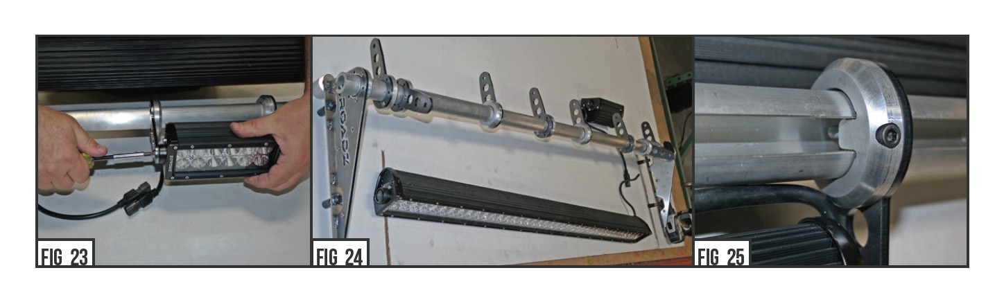
Your kit was shipped with a universal length cross member tubeO. n some vehicles the bar length may be longer than required for your vehicle and if you desire, cut the tube to fi ytour vehicle. The way to determine the measurement is to find the distance from the outside edge of the roof channel, toth e opposite outside edge of the roof channel.A dd 1” and that is the measurement you need to cut the ba.r Cold cutting is recommended but using a band saw or hand saww ith metal cutting blade will also suffice.T he supplied end cap will hide the cut edge once you completeh te installation.
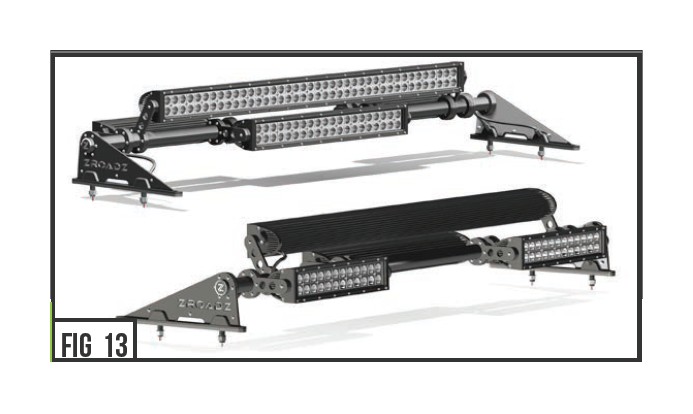
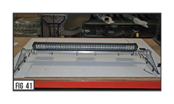
6) It is now time to mock up and determine your LED Light layout nad configuration. Put the parts in place starting with the Cross MemberT ube and Upright Mounts. Add and position LED Lights into your layout mock as you desire. Fit and match the Bracket Assemblies so that the layout resembles your preferred plan. NOTE: Customize and build according to your needs and preference. There are literally dozens and dozens of configurable combinations to organize and stack LED Light Bar placement, facing forwards, backwards, left & right. Leave at elast 1.5” Tube on each end
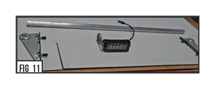
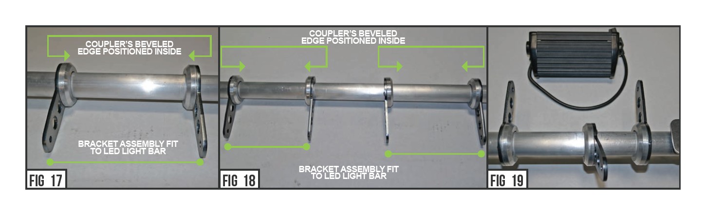
7) With Your LED Light positioning determined and finalized, go ahead and slip the appropriate Bracket Assemblies onto the Cross Member Tube.
Make sure each bracket/coupler assembly is installed on the ba rwith the bracket and exposed button head Allen cap screws towards the outside of the LED light assembly as shown in Fig. 17, 19.
8) Fit and match the Bracket Assemblies so that the layout resembles your preferred plan.
9) Some Bracket Assemblies may be pointed forwards, backwards, and also clocked up if your original layout called out for this configuration.
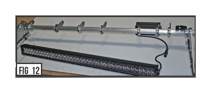
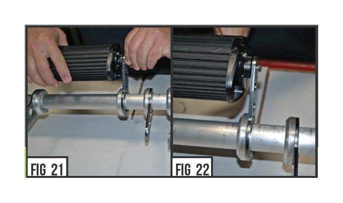
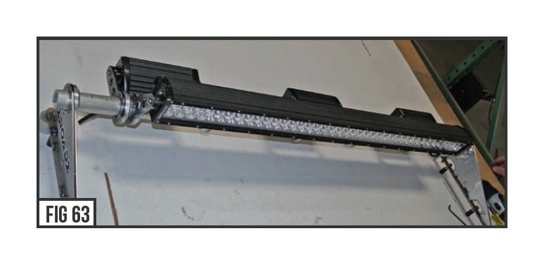
10) Go ahead and mount the LED Lights into their designated position and secure to the Bracket Assemblies.
11) With your LED Light positioning determined and finalized, go ahead and measure the LEDs placement side to side for approximate centering and equal symmetry
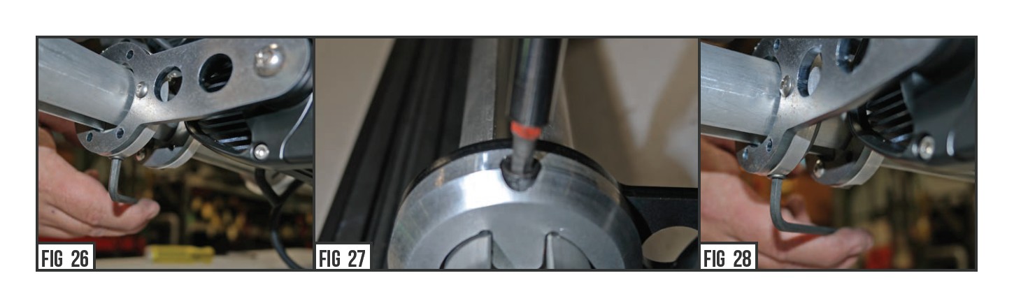
12) Once your satisfied with your LED placement, lock the Bracket Couplers into place by tightening the (Steel Thread Allen Cap) set screw on the underside of the Couplers
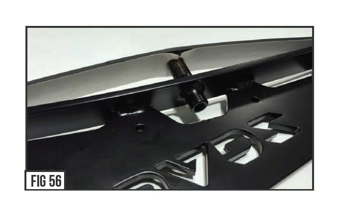
13) It is now time to plumb and wire the LED Light Wiring inside teh hollow cavern of the Cross Member Tube’s under belly. Start by slipping the one of the 1/2” Rubber Sealing Washers (From Bag #6) onto each of the LED Light Wires.
14) To help push the rubber washer also the LED Light Wire into plcae, we recommend using some 50 / 50 water / dish soap lubricating solution to easily plumb the wires. With the 1/2” Rubber Sealing Washers slipped over the wires, carefully tuck it to the side of the Bracket Couple’rs Set Screw. Press and insert the 1/2” Rubber Sealing Washers into the Cross Member Tube’s Under Belly.
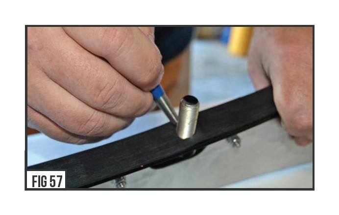
15) The purpose of the 1/2” Rubber Sealing Washers around the LED Light wires is to hold and secure the wires inside the hollow caverno f the Cross Member Tube’s under belly.
16) Note that Modular Roof Mounts configured with an assortment o f LED Lights will have multiple wires plumbed through the Cross Member Tube. For this reason, you may have to plumb some wires to the rdivers side and some to the passenger side.
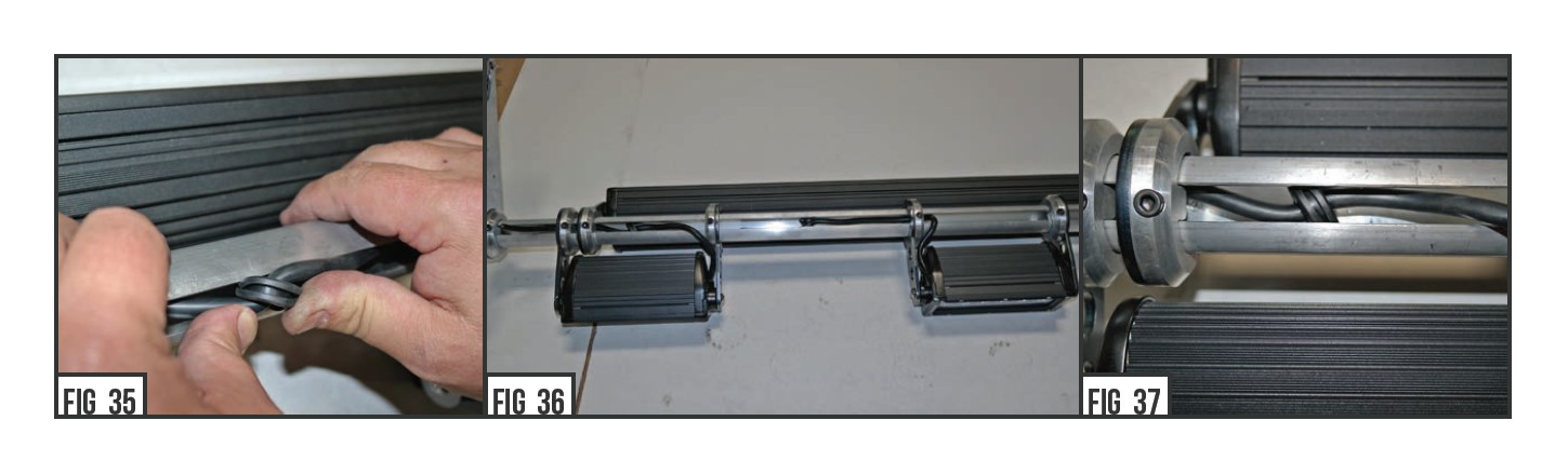
17) If there is more than one wire, slip one wire to one side of teh Set Screw and than slip the other wire to the other side of the set screw
INSPECT YOUR WORK
The Bracket Assemblies should be locked into place, the LED Lights should be mounted, and the LED Light wires should be cleanly plumbed into the Cross Member Tube’s under belly.
18) At this point, you will need to dissemble the Upright Mounts from the Assembled Modular Rack so you can accurately install the Upright Mounts onto Vehicle Roof. DO NOT attempt to install Upright Mounts with Assembled Modular Rack onto Vehicle Roof.
MODULAR RACK INSTALL - START
19) It is now time to begin the process of preparing the vehicle for install. This can be a delicate and pain staking process so make certain that you have the appropriate tools and know how
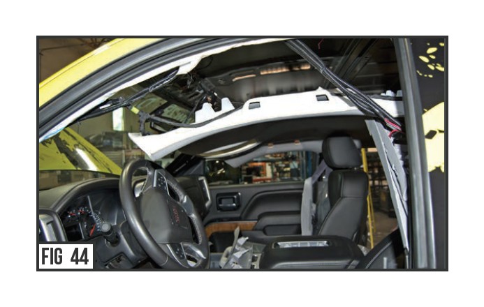
20) Drop OEM headliner down to allow access to the inside of vehicle roof panel moulding, per industry “R&R“ method.
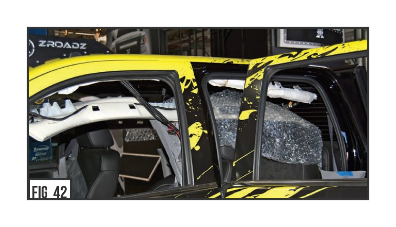
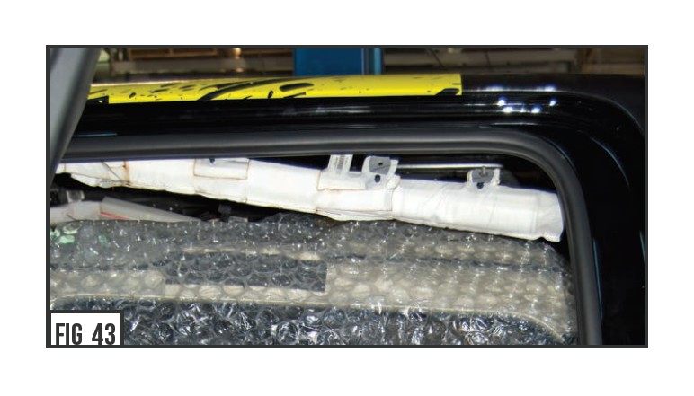
21) Carefully push to the side and clear any of the now exposed vehicle components such as side / curtain air bags, wiring looms, inteior r plastics, ect.
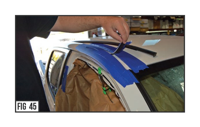
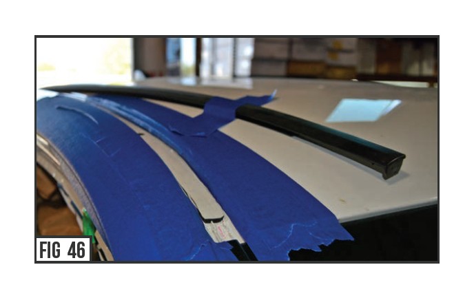
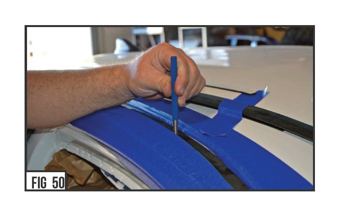
22) From above, remove or push to the side roof seam moulding (if your vehicle comes equipped).
23) Using the provided templates, put them into place inside the vehicle’s roof channel to help determine where the drill holes will locaet.
IMPORTANT
Prior to marking the vehicle for drilling you must first checko fr clearance on the inside of the vehicle roof for the bracket mounting threaded down tubes. You can achieve this by inspecting the inside of the vehicle roof channel once the headliner is removed. Make sure that the location of the main upright brackets will not interfere with any substructure, accessory mounting tabs, airbag mounting tabs, wire harness mounts, or similar. Find an acceptable placement of the brackets, mock up with provided template and proceed to mark the roof channel for drilling.
24) Test fit Bracket Mounts positioning according to the template placement.
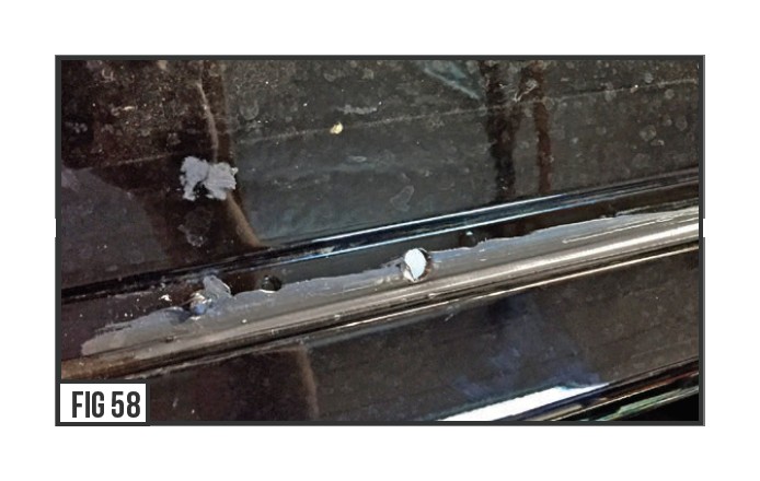
For Ford trucks it is not necessary to remove the moulding or seam sealer. Drill hole through body seam sealer. Use RTV silicone to fill any uneven surfaces around drill hole prior to installing the bracket to the vehicle.
Clear the channel of any obstructions including any channel moulding mounting posts where the bracket will install. If the channel has body seam sealer that does not span the width of the channel it must be removed for the distance that the bracket will come in contact with the roof channel. Replace any seam sealer with RTV silicone (STEP #29) and apply in a manner that yields a flat surface for the gasketto contact the roof.
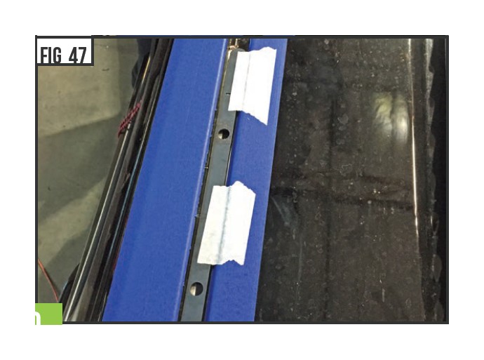
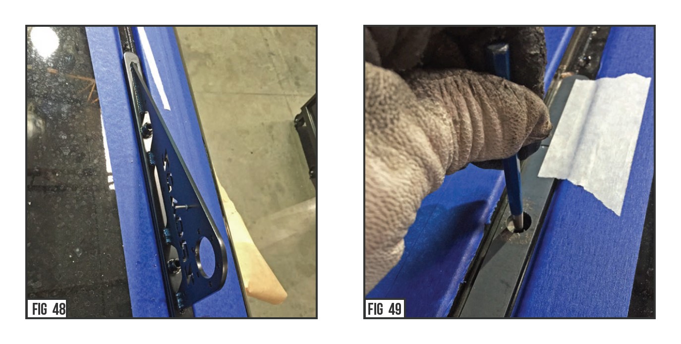
25) Make sure the template is centered in the width of the channe lu, se masking tape or similar to hold the template in place prior to center punching the roof for drilling. Center punch the locator marks through the template.
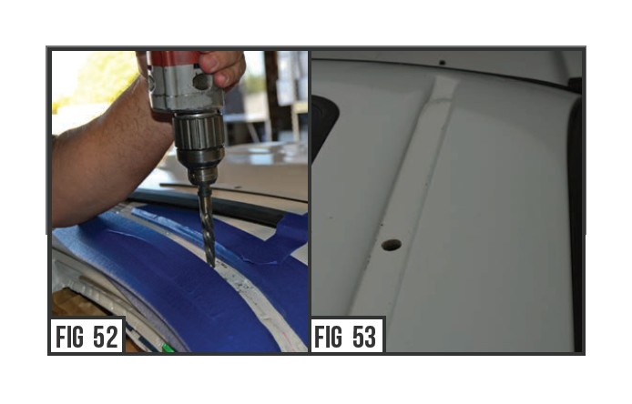
Drilling vehicle roof
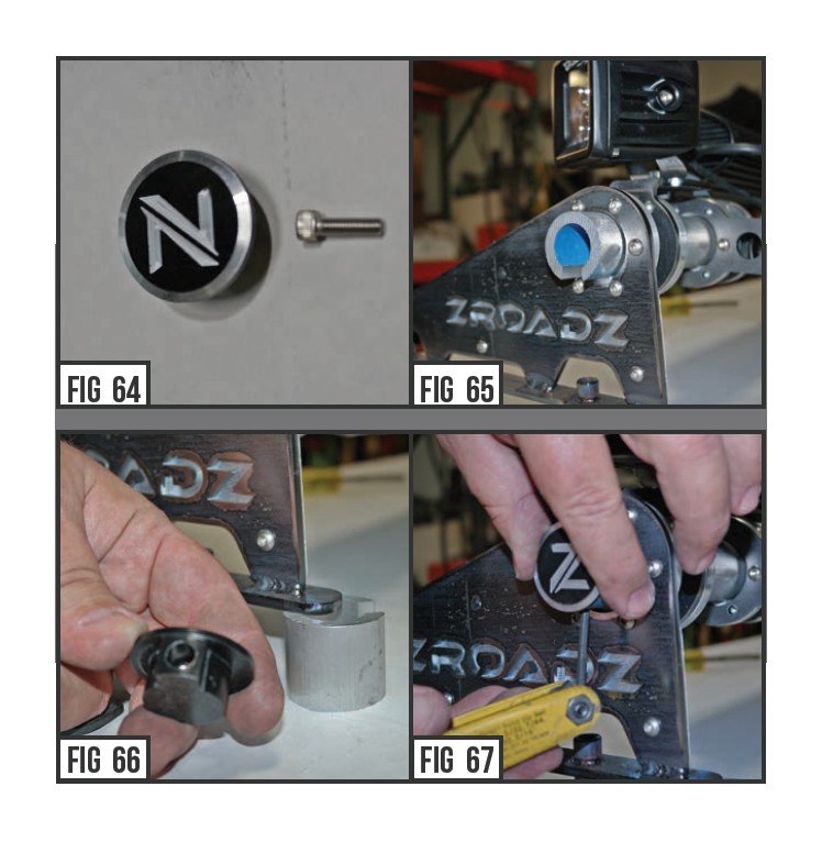
26) With the interior roof free and clear, drill a 1 /4” hole in the roof channel gutter to pilot the mounting hole. Use a car reamer (as seen in Figure #7) or tapered 1 /2” metal drill bit to open the hole to a final diameter of 1/2” . Drill the holes and check that both right and left uprights fiitn to the channel and are free and clear to seal along the base of the roof channel. With the holes drilled through, clean off all drilling debris and flash INSIDEA ND OUTSIDE OF THE DRILL HOLE LOCATIONS. This is a very important to create a flush sealing surface and you do not want to leave any chance o rfust occurring. Perform this step for both sides of the roof.
27) Clean the base of the supplied Upright Mount with alcoho l. Once dry remove the liner of the base gaskets and apply the gasket to the base of each bracket.
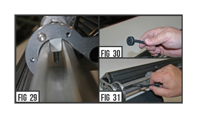
28) Before you install the Upright Mount to the roof, check that the threads on the post are clean.
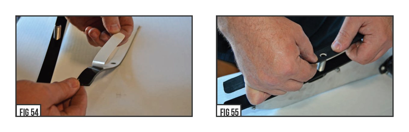
29) Use a thin layer of clear RTV Silicone around outside of each drilled hole to help with weather proofing and sealing.
Install roof mount to roof
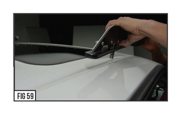
30) With the roof and channel area debris free and wiped down clean with alcohol cleaning solution, align the ZROADZ Modular Roof Upright Mounts to the roof and insert the through bolt threadsd own into the drilled hole.
Make sure the outside of the Upright Mount is coated black and says ZROADZ while the inside of upright presents the aluminum skin.I nspect your work to make sure you are happy with the position and then repeat for other side.
31) Loosely install the Upright Mounts to the right and left sides of the Cross Member Tube. It will be heavy with all the LEDs installed so grab a friend to help install the completely assembly Cross Member Tube between the Upright Mounts.
Center the Cross Member Tube between the Upright Mounts and now finally lock it into place by tightening down the Outside Couplers at the Upright Mounts.
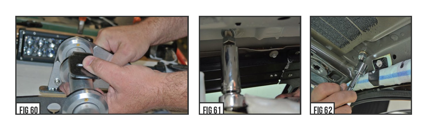
32) With the two Upright Mounts placed into the drilled holes andh te Cross Member Tube centered and seated, check that the threads on the post after coming through the roof are clean and free from debris.
Install the split lock washer and the (4) 1/2” hex nuts (From Bag #3) and tighten securely. Check to make sure the upright is secured and firmly attached to top side of roof.
33) At this point you are ready to insert and secure the Modular Cross Member Tube End Caps. Using the provided hardware and parts (from Bag #5) put the End Caps into place and than insert the (2) - 1#0-32 x .625 Stainless Steel Socket Cap into the pre-determined hole and tighten down using an Allen Wrench or something of the sort. The Modular Rack should now be fully assembled, and firmly installed on the Vehicle’s Roof.
INSTALL END CAPS
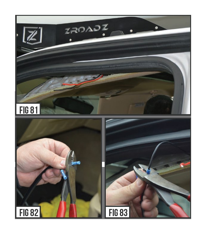
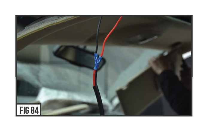
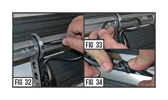
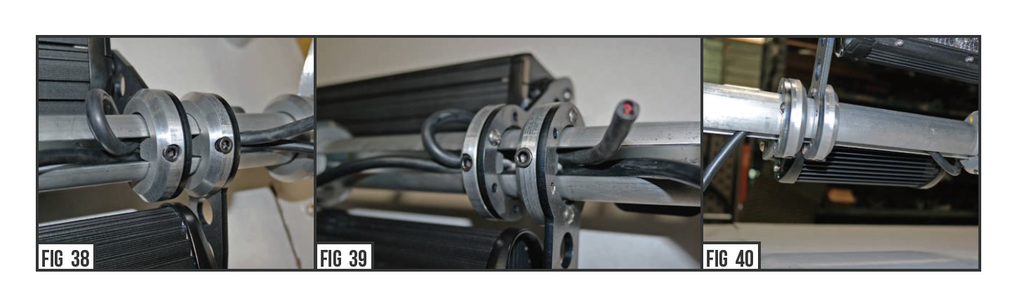
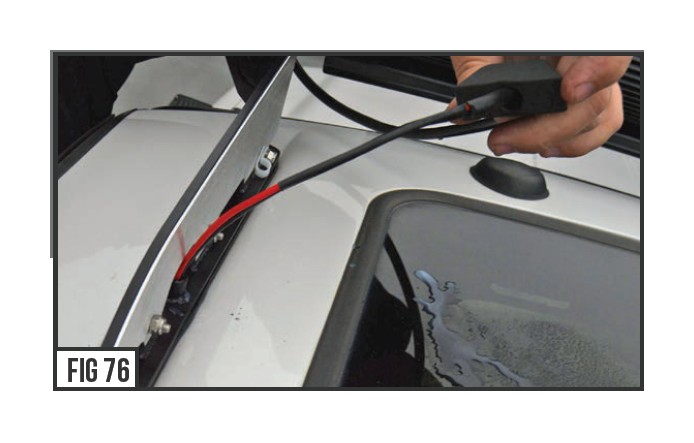
34) Secure the wire to the Upright Mount with supplied wire clip and nut ( From Bag #4 ). Leave slack in the wire from LED to the wirel icp for some movement & available adjustment. Cut the LED light wires. Leave enough room for the insulation to be removed and the red and black weirs to pass though the roof via the “Through Bolt DownT ube”.
35) Trim back a large amount of the insulation sheath off the LED Wires so that you can slip them through the rubber weather proofing bot. To expose the wires, Wire Strippers will do the trick.
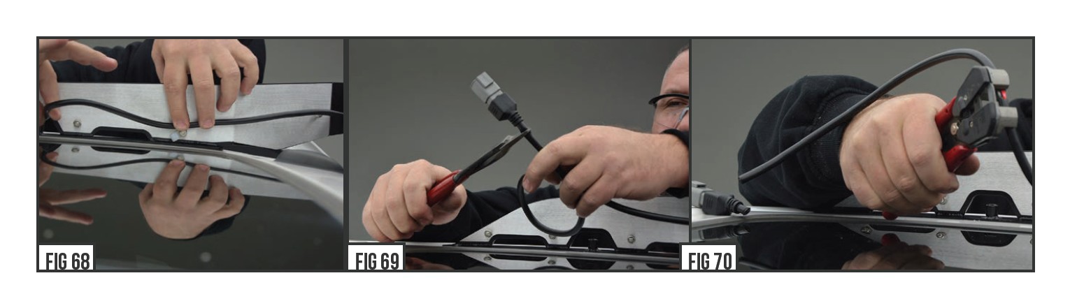
36) Install 1/4” heat shrink insulation over wires as shown in Figure #25. Shrink insulation with heat gun or similar
Wiring plumbing
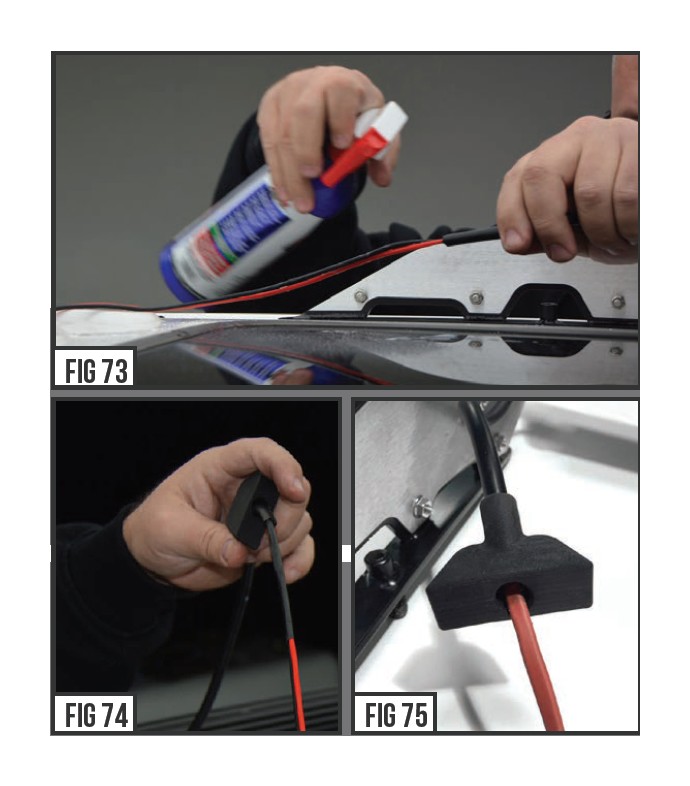
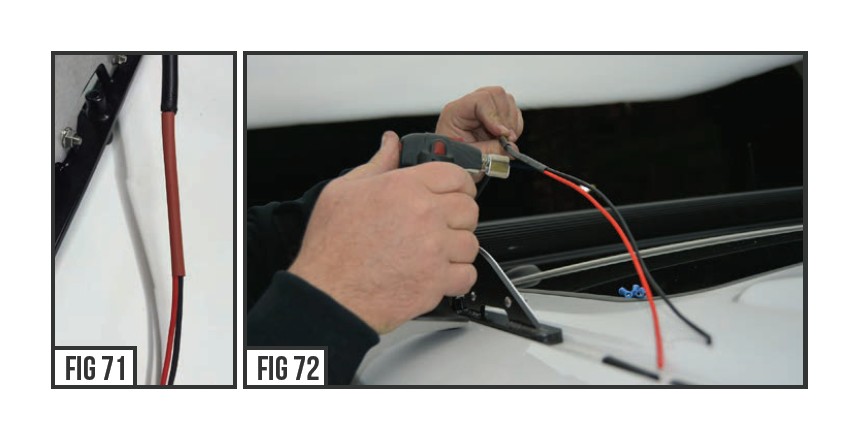
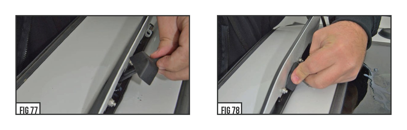
37) Use a 50/50 mix of dish soap and water solution to install supplied boot over wire as shown on page #2 Fig. 6.
Pass the wire though the tube. Use a liberal amount of solution on the bracket around the area where the boot installs to aid in slipping the boot overh te post.
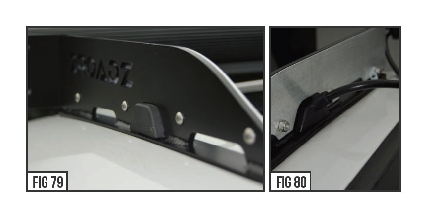
38) Stuff the boot into the bracket opening and over the down tube upright. Repeat these steps for any other remaining exposed wires, and also use the (3 if needed) Wire Boot Plugs to finisho ff the blocking off the gaps and fully weather proofing the Upright Mounts.
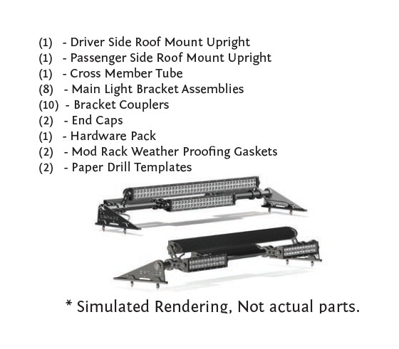
39) With the rubber boots fully seated, you are now ready to finish wiring up the LED Light bar to a wiring harness .
After wiring is complete, re-install vehicles’ interior in the reverse order it was removed according to industry “R&R“ method.
40) Wire LED Light with a ZROADZ optional wiring harness kit (part# Z390020S-A) or by utilizing a compatible custom wiring harness .ZROADZ recommends LED Lights be wired with ZROADZ harness kit (part# Z390020S-A).
41) To adjust the angle of your Light Bar, rotate the LED(s) to adjust the angles till your desired light pattern is reached.T here will be minimal adjustment due to curved light bar orientation. You may than tighten the hardware and secure everything into place. Be careful not to over tighten the mounting hardware.
It is best to adjust the angle with the vehicle on level groun dwith lights facing a wall, garage door or other solid barrie.r We recommend checking from a distance of 25’. Your installation is now completed.
Final Installation