FREE 1 to 3-Day Delivery on Orders $149+ Details

How to Install N-Fab Wheel to Wheel Nerf Steps - Matte Black (12-17 Wrangler JK 2-Door) on your Jeep Wrangler
Installation Time
1 hours
Tools Required
- 3/8" or 1/2" drive ratchet wrenches
- Socket wrench sizes: 9/16"
- Open end/ combination wrench sizes: 9/16"
- Flat head screwdriver
- Jack stands, or a second pair of hands
- Loctite(Medium removable strength if you plan on reversing your nerf bars, permanent strength if you do not plan on removing your nerf bars. Apply before assembling hardware)

Shop Parts in this Guide
Olympic 4x4 Products are serviced by our factory. We provide ans,,vers to installation questions. We ship parts ASAP. Try us before the hassle of returning Olympic 4x4 Products to your retailer or mail order specialist. May not be compatable with some aftermarket suspension systems. Flare extensions must be removed to use reverse bar In up position.
Note: Even though we provide Nylock nuts which are vibration resistant we suggest using loctite on all mounting hardware
Step 1. The long leg goes in the front of the jeep, the short one goes towards the rear of the jeep.
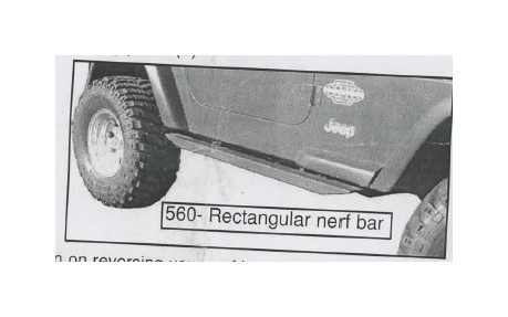
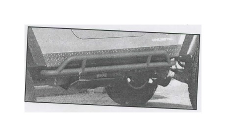
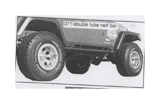
Note: You can install the nerf bar with the angular tuba pcintlng up or down. You can switch them even after you install it. For serious rock crawling, install the tube pointing up so it pro-vides extra protection for your rocker panels. For mild off-roading or to be used as a step, install the nerf bars with the tube pointing down. Rectangular nerf bars cannot be flipped.
Step 2. Position the nerf bar so that the mounting bracket sits flush against the vehicle frame. Make sure both mounting brackets are flush against the frame.
Note: You will find that you have a small amount of adjustment so you can decide the exact position you prefer.
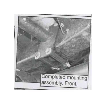
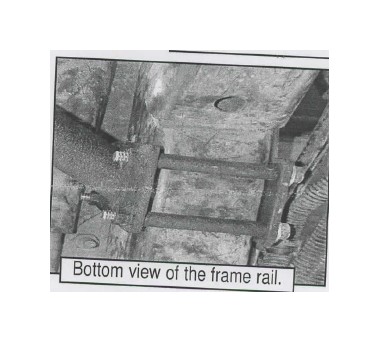
Step 3. (Front mounting) Place one of the four mounting plates on the inside of the vehi-cle frame and pass a 3/8" X 3 1/2" hex head bolt through a flat washer then through the bracket on the outside of the vehicle frame, across the vehicle frame, through spacer tube, and through the flat bracket on the inside of the vehicle frame. Secure with a 3/8" flat washer and nylock nut. Finger tighten bolts at this time.
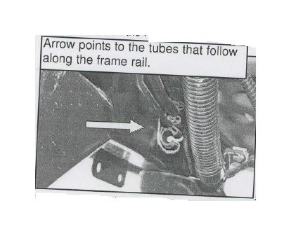
Note: On some newer Wranglers, the rear mounting plate with the hole in the center that mounts on the drivers side must be installed between the vehicle frame and the tubes that run along the frame rails. To do this you must first remove the snap-in holder with a flat head screw driver, place the mounting plate with the hole in the center in place then the snap-in holder will fit inside the hole in the mounting plate. The white arrow points to the spot where the tubes are mounted to the frame.
Step 4. (Rear mounting) Place the second mounting plate inside the frame across the second mounting bracket, pass a 3/8" X 3 1/2" hex head bolt through a lock washer, then flat washer then the bracket on the inside of the vehicle frame, across the vehicle frame, through spacer tube, secure the 3/8" hex head bolt by threading it into the nerf bar mounting bracket. Finger tighten all bolts, then securely tight all bolts once every-thing is in place.
Step 5. Repeat steps 2-4 for the opposite side of your jeep.
Step 6. Re-check tightness on ALL nuts and bolts. Periodically check tightness on ALL nuts and bolts.