 FREE 1 to 3-Day Delivery on Orders $149+ Details

How to Install Zone Offroad J-Flex Adjustable Front Upper Control Arm for 0-6 in. Lift (07-18 Wrangler JK) on your Jeep Wrangler
Tools Required
- JKS1696 or equivalent jam nut wrench
- Hydraulic Floor Jacks (two required)
- Jack Stands
- Metric/Standard Socket Wrench Set
- Torque Wrench
- Tape Measure
- Anti-Seize Lubricant
- Hand-Pump Grease Gun
- Moisture Resistant Marine Style Grease
- Heavy Duty Ratchet Strap *
- Factory Service Manual (recommended)

Shop Parts in this Guide
Welcome
CONGRATULATIONS on purchasing a set of new Adjustable Control Arms from JKS Manufacturing. We are committed to providing you with the best products available and your satisfaction is our first priority.
PLEASE READ these Installation Instructions carefully, and save them for future reference, as they contain important installation and maintenance information.
Important
SUSPENSION COMPONENTS THAT HAVE RUBBER BUSHINGS must be tightened with vehicle on level ground and at normal ride height. The springs must be supporting weight of vehicle when the hardware is torqued.
RUBBER BUSHINGS MUST NEVER BE LUBRICATED, as doing so will impair performance and longevity.
COMPATIBLE WITH original 4-link suspension configuration and vehicle ride height up to 6.0”.
REFER TO FACTORY SERVICE MANUAL for information and procedures not covered in these instructions.
ATTENTION INSTALLER
Install Adjustable Control Arms ONE AT A TIME for easiest alignment of mounting hardware.
Installation
1. REMOVE ORIGINAL UPPER SUSPENSION ARM
Raise and support the vehicle chassis with jack stands positioned behind the front lower suspension arm brackets.
Raise the axle housing back into position and support with a hydraulic jack. HINT: The axle housing should be evenly supported and the suspension at normal ride height. Do not attempt removal or installation with the suspension extended, or the axle drooped, as this will place tension on suspension arm mounting hardware.
Remove the electrical clip from the suspension arm clevis bracket if equipped.
Remove the upper suspension arm nut and bolt from the axle housing bracket. Retain the original mounting hardware.
Remove the nut and bolt from the chassis rail bracket. Retain the original mounting hardware. See year specific notes below.
2007-2011 models with 3.8L engine: To remove the passenger side bolt from the chassis, it will be necessary to raise the engine according to the following instructions
Position a second hydraulic jack beneath mounting flange of engine oil pan. Support engine using a suitable block of wood (2x4 or larger) to distribute weight across oil pan bolts. DO NOT attempt to lift the engine by engine oil pan.
Carefully raise the hydraulic jack just enough to remove the weight of the engine from the engine mounts.
Locate the passenger side engine mount bracket and remove the four (4) bolts that secure it to the engine block.
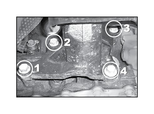
Slowly raise the hydraulic jack approximately 1-2 inches until the passenger side control arm bolt clears the interfering exhaust pipe.
Continue following instructions with engine in raised position and begin Control Arm install
2012 models with 3.6L engine: To access the frame bolts, it will be necessary to remove the heat shields from both upper control arm frame mounts.
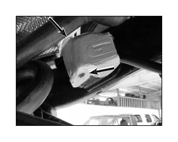
Remove the 2 bolts per heat shield, one on top and one onthe bottom using a 10mm ratchet wrench.
Remove the original upper suspension arm from the vehicle.
2. SET CONTROL ARM LENGTH
Determine the ideal arm length for your application by considering factors such as:
Pinion Angle / Caster
Tire / Steering Clearance
Factory length is 18-3/4"
Max. length is 20-1/4"
Set both control arms to the same length. Lengthening the arms will reduce caster and increase pinion angle.
3. INSTALL CONTROL ARM
Apply anti-seize lubricant to bolt threads of original mounting hardware.
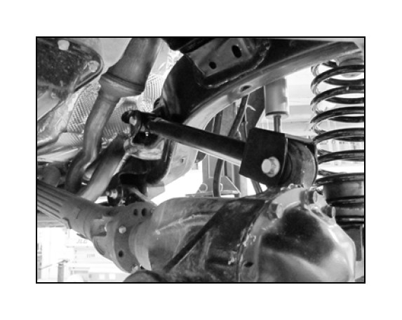
Mount the fixed end of adjustable control arm to the axle housing bracket.
Mount the flex end of the adjustable control arm to the chassis bracket with the greaseable fitting facing down.
Install the original mounting bolt from inboard side. Bolt threads should point outboard.
2007-2011 models with 3.8L engine: Passenger side bolt must be installed with engine in the raised position to provide sufficient clearance around exhaust pipe.
With the Control Arm positioned in the chassis rail bracket, insert the original bolt into the mounting hole.
Carefully lower the hydraulic jack until the passenger side engine mount support bracket is realigned with the engine block.
Install the four (4) original bolts into the corresponding mounting holes and tighten to 45 ft-lbs. using a torque wrench.
Lower the hydraulic jack and remove block of wood from beneath engine oil pan.
Install the original mounting nut and finger tighten. DO NOT torque mounting hardware until instructed.
Install the original mounting bolt from inboard side. Bolt threads should point outboard.
Install the original mounting nut and finger tighten. DO NOT torque mounting hardware until instructed.
HINT: If mounting bolt is difficult to install due to misalignment of Control Arm bushing with mounting bracket, either (1) adjust height of axle housing with hydraulic jack, (2) move axle housing into position with a heavy-duty ratchet strap, or (3) temporarily disconnect track bar until mounting holes align.
4. TIGHTEN MOUNTING HARDWARE
Once both control arms have been installed, torque the frame mount hardware to 75 ft-lbs.
2012 models with 3.6L engine: Re-install the heat shields that were removed from the control arm mounts.
Once both frame mounts are torqued, lower the vehicle to the ground until coil springs are supporting the full weight of vehicle.
Using a torque wrench, tighten the axle mount hardware to 75 ft-lbs.
Tighten the jam nuts using JKS1696 or equivalent.
5. POST-INSTALLATION INSTRUCTIONS
Installing longer upper control arms will affect the vehicle alignment by reducing caster. This may also slightly affect the steering wheel position, making it off-center. It is important that the steering wheel is centered to avoid adverse affects on the vehicle's electronic stability control (ESC) system. JKS recommends having the alignment check by a qualified alignment shop.
Check mounting hardware for proper torque.
Check hardware after 500 miles of use.
Maintenance
Control arm flex ends should be greased regularly as part of vehicle maintenance schedule or after every 4-wheeling trip. Lubricate using marine grade grease.
