FREE 1 to 3-Day Delivery on Orders $149+ Details

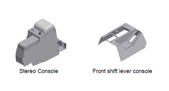
How to Install a Tuffy Universal Black Stereo Security Full Console Series II on your 97-06 Wrangler
Installation Time
30 minutes
Tools Required
- (1) ½” wrench or ratchet, socket, and extension
- (1) ½” wrench
- (1) 7/16” wrench
- (1) 3/8” wrench or ratchet, socket, and extension
- (1) 5/16” wrench
- (1) ¼” Wrench
- Phillips head screwdriver
- 3/8” drill bit
- Electric drill
- Silicone sealant (not necessary but recommended)
- For stereo installation an antenna wire extension

Shop Parts in this Guide
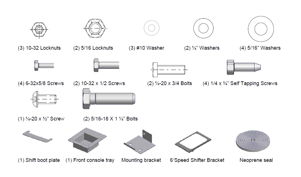
SHIPMENT CONTENTS
Shipping Package
Installation
1. Please read all instructions before starting installation.
NOTE: IF YOU’RE VEHICLE HAS HAD A SUSPENSION MODIFICATION WHICH HAS ALTERED THE STOCK SHIFTER LOCATION THE SHIFTER MAY HAVE TO BE BENT BACK TO ITS ORIGINAL POSITION, OR LENGTHENED, TO AVOID HITTING THE CONSOLE WHEN SHIFTING GEARS. CHECK FIT BEFORE PERFORMING INSTALLATION.
2. It is recommended to use silicone sealant on any mounting points to vehicle body to prevent future rust problems.
3. Removing one or both of the seats will make installation easier.
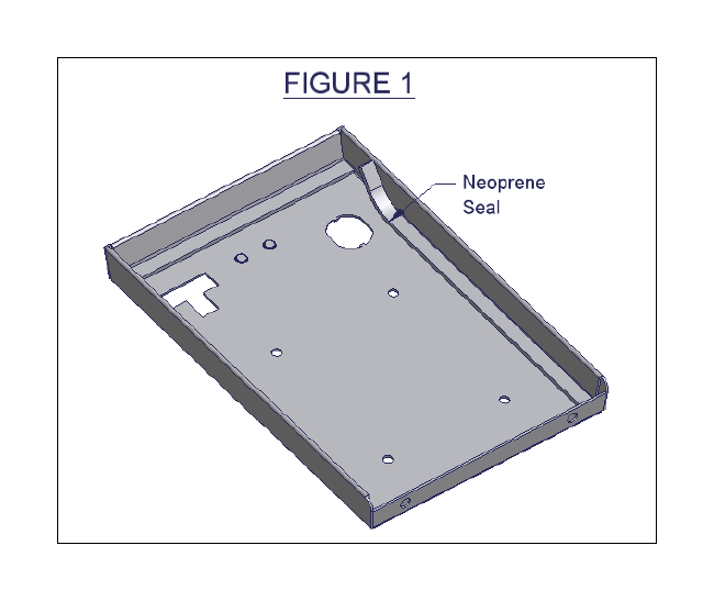
4. Apply the rubber seal to the underside of the main compartment lid and the front compartment lid. (SEE FIGURE 1)
5. If you do not have a factory console, remove the rubber emergency brake cover. Otherwise remove the (6) self-tapping screws from the factory console. Two are located inside the console (or, in 2001& up, under the rubber inside the rear drinkholder), two are on the passenger’s side along the bottom, one is in the front cup holder, and one is under the gear shift boot (shift boot can be removed by gently pulling the plastic base up out of its mounting hole). Save these screws because you may reuse some of them.
6. In vehicles equipped with the air bag switch it can be removed without disconnecting wires. To do this push or pull the faceplate out of the original console and then maneuver it back through the opening it came out of. In 2003 TJ’s the tray from the original console should be removed and reused.
7. If you are mounting a stereo or other electronic equipment in the front compartment run the necessary wires to the spot between the seats where the console will be mounted. (An antenna wire extension may be necessary for installation (not included), it is available at most Radio Shacks and other electronic parts supply stores)
Warning! Make sure that there is nothing under the vehicle that will be damaged by the drill bit when drilling.
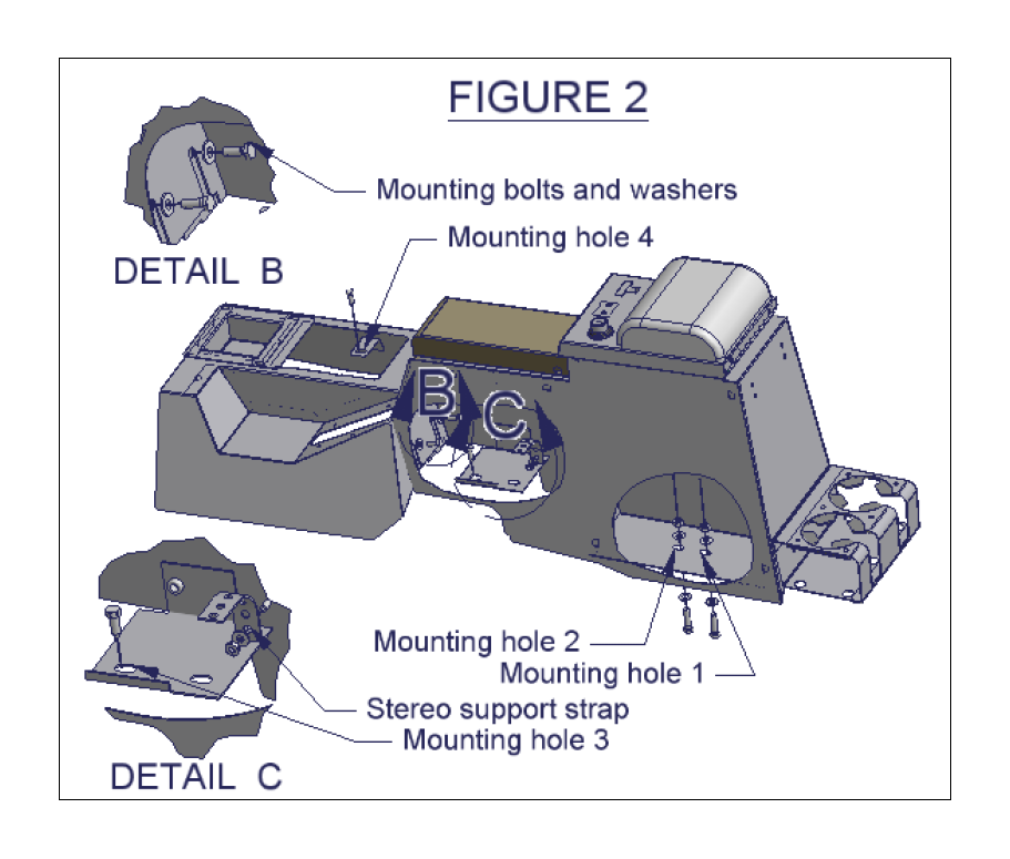
8. Drill out the two original mounting holes (HOLES 1 AND 2 IN FIGURE 2), located on the floor of the vehicle, to 3/8” diameter. (In 2001 and newer TJ’s these holes (1 and 2) may not already be in the floor and will have to be drilled)
9. Install the mounting bracket using a ¼-20 x ¾” self tapping screw. (HOLE 3 IN FIGURE 2)
10. Install the Tuffy console by guiding the console over the emergency brake; be careful not to tear the seats.
11. If applicable, install your stereo or other electronics in the console and connect all the required wires. The rear of the stereo can be fastened to the stereo support strap, which is fastened to the console using a 10-32 locknut and washer. (SEE FIGURE 2 DETAIL C) (Consult electronics owners manual for connections)
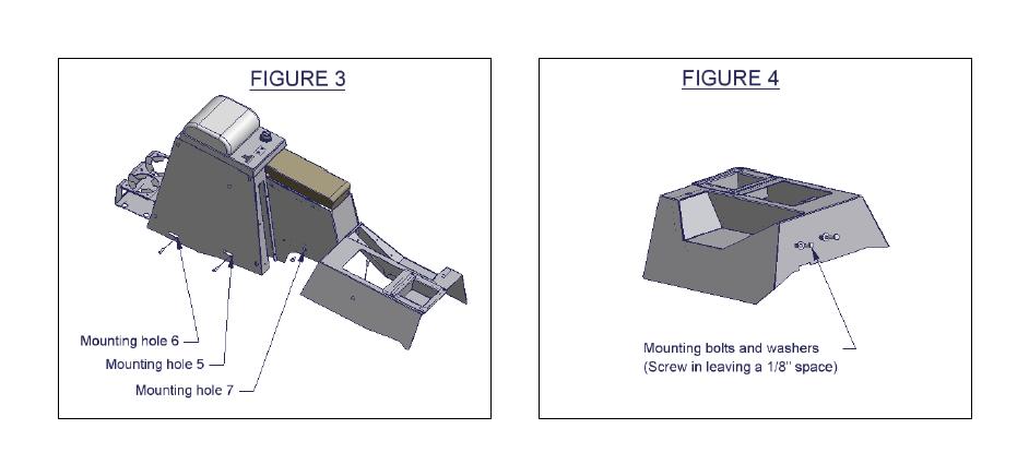
12. Before installing the front shift lever console, screw (2) ¼-20 x ¾” bolts with washers into the shift lever console, do not tighten them all the way leave about 1/8” gap. These are used as guides. (SEE FIGURE 4)
13. Install the front shift lever console over the 4WD shifter. Moving the levers into different locations may make installation easier. Be sure emergency brake is on. Be careful not to rip the gearshift boot, tear the seats, or scratch the dash.
If the vehicle is equipped with an air bag switch (In 2003 and newer TJ’s the tray from the original console should be used)
14. The switch can be installed without disconnecting any wires. To do this, maneuver the air bag switch faceplate up from the bottom through the opening in the console then snap it into place.
15. Attach the front shift lever console to the stereo console by sliding the slots in the front of the stereo console around the (2) 1/4- 20x3/4” bolts. If the bolts are accessible tighten them until they are snug. (SEE FIGURE 2 DETAIL B)
16. Line up all of the mounting holes and make sure no wires are pinched under the console.
17. Bolt the stereo console to the mounting bracket previously installed under the front compartment using a ¼-20 x ½ screw. (HOLE 7 IN FIGURE 3)
18. Insert the (1) ¼-20 x ¾” screw in the bracket under the gearshift boot in the front shift lever console (HOLE 4 IN FIGURE 2). In 1997 – 2000 TJs - Insert (2) ¼-20 x ¾” screws in the passengers side of the console. (HOLES 5 AND 6 IN FIGURE 3)
19. Bolt the console down using the (2) 5/16” bolts, (2) 5/16” nuts, and (4) 5/16” washers (IN HOLES 1 AND 2 IN FIGURE 2); push at least one bolt up from the bottom for added security.
20. Reinstall shift boot cover. If the vehicle has an automatic transmission the shift plate should be installed by pushing the ears on the plate through the corresponding slots in the console then sliding it toward the rear of the vehicle to hold it in place. To secure the shift boot do the following applicable steps.
If the vehicle is equipped with the air bag switch (In 2003 and newer TJ’s the tray from the original console should be used)
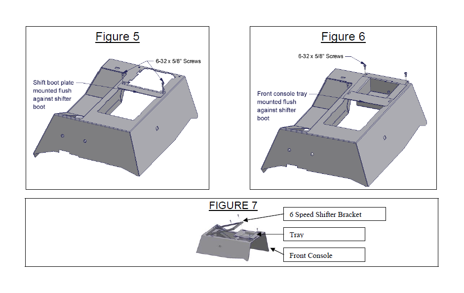
21. Attach the shift boot plate to the console using (2) 6-32 x 5/8 screws (SEE FIGURE 5). Position the shift boot plate flush against shift boot so it holds the shift boot tightly.
If the vehicle is not equipped with the air bag switch
22. Attach the front console tray using (4) 6-32 x 5/8” screws (SEE FIGURE 6). Position the tray flush against the shift boot so it holds the shift boot tightly.
If the vehicle is equipped with a 6 speed manual transmission.
23. Place the front console tray in the cutout. Then sandwich the Original shift boot between the Front Console and the 6 Speed Shifter Bracket. Fasten everything down with (4) 6-32 x 5/8” screws (SEE FIGURE 7).
24. Check lock operation. The rubber seal will need to be compressed initially and will wear-in with time.