FREE 1 to 3-Day Delivery on Orders $149+ Details

How to Install Tuffy Single Compartment Overhead Console on your 2007-2013 Wrangler
Tools Required
- 1/8" Allen Wrench
- Small Phillips Screw Driver
- Ratchet and 1/4" socket
- 3/8" socket
- 10mm socket
- 1/2" Deep well socket
- extension and Ratchet – Swivels are helpful (Vehicles with full Roll Cage only)

Shop Parts in this Guide
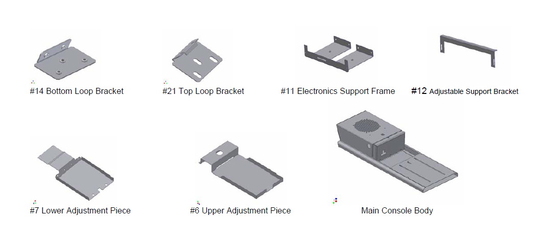
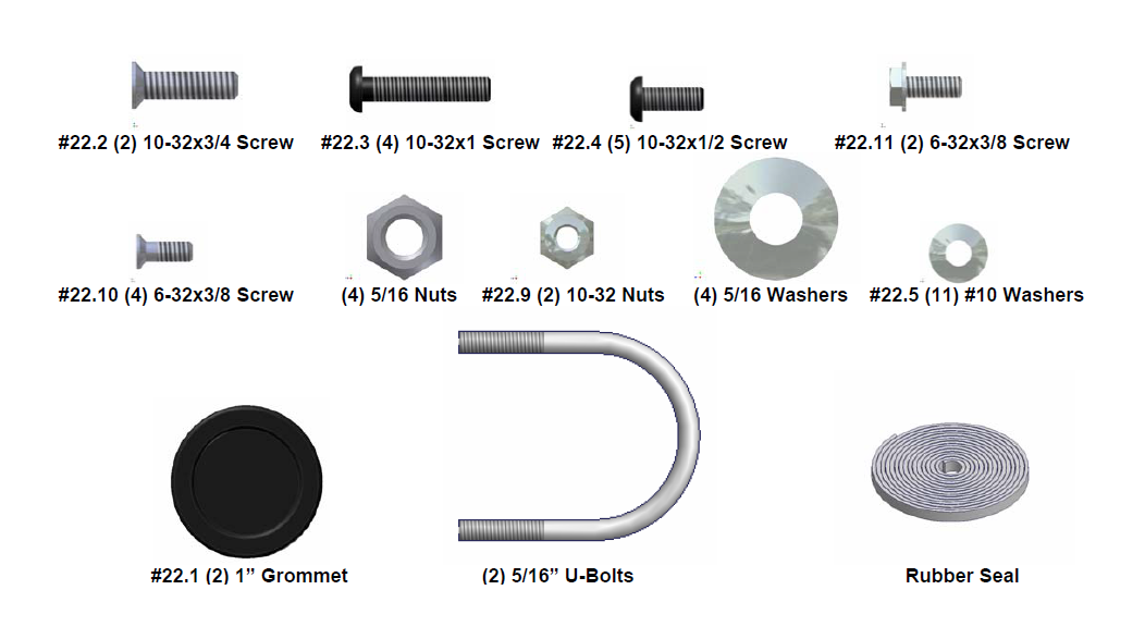
Shipment Contents
Shipping Package
PLEASE READ ALL INSTRUCTIONS THOROUGHLY BEFORE STARTING INSTALLATION.
1. Apply the Rubber Seal provided to the lid so that it will seal up against the console when closed. Check the lock operation.
Vehicles with a bikini top
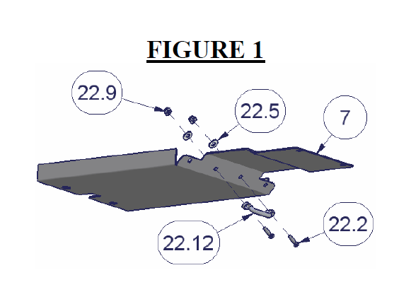
2. If you have a bikini top or if you plan to get a bikini top, you will need to purchase a footman loop. Most hardware stores have footman loops in stock- You will need one with hole spacing of 2-1/4” center to center. (See #22.12, Figure 1)
3. Using #22.2 (2)10-32x3/4 Flat head screws, #22.9 (2)10-32 Nylock nuts, and #22.5 (2) #10 Washers bolt the footman loop to the Lower Adjustment Piece. (See Figure 1)
4. Remove the hard top and “T” tops (or lower the soft-top). Consult your vehicles owners’ manual for removal instructions.
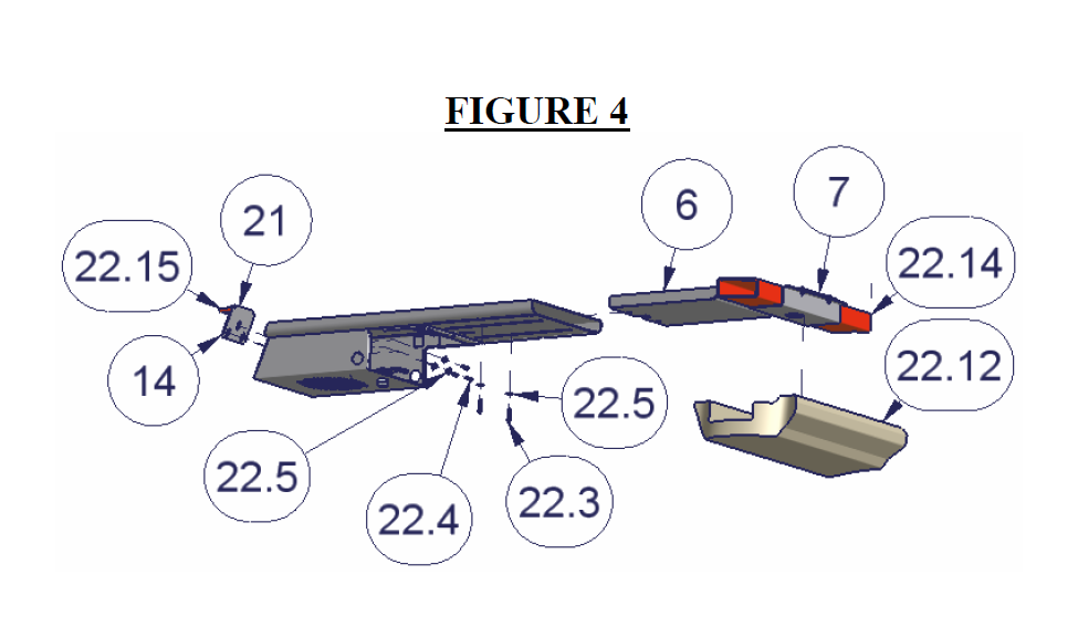
5. Remove the #22.12 factory sound bar by removing the 6 mounting screws and unplugging the wiring harness. Save all this hardware it will all be reinstalled. (See figure 4)
6. Route the wires for your stereo, CB, or speaker up along the roll bar and leave plenty of extra wire.
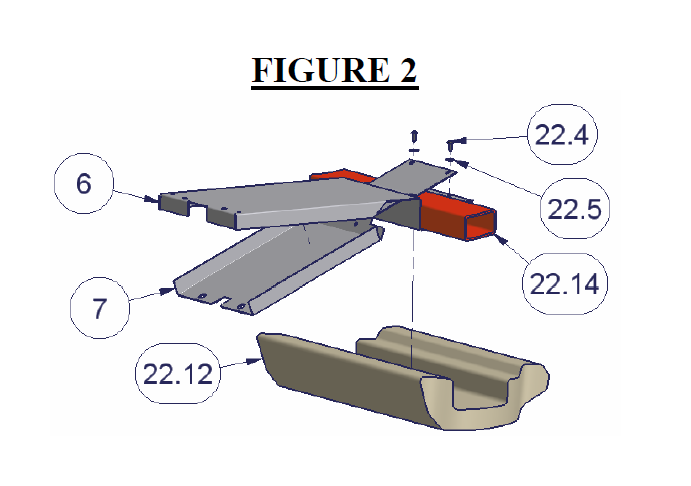
7. Place the #6 Upper and #7 Lower Adjustment pieces around the #22.14 rear roll bar lining up the hole on the bottom of the roll bar up with the hole in the Lower adjustment piece. Route the previously run electrical wires from the roll bar through them.
Notice that the lower piece slides through the slot on the upper piece. Fasten the two together using #22.4 (2) 10-32x1/2” socket screws and #22.5 (2) #10 Washers. Only start the screws a few turns. (See Figure 2)
Follow these instructions for standard mounting in an unmodified vehicle. If the vehicle has a full sport cage skip this section.
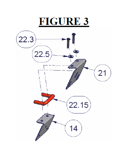
8. Install the #21 Top and #14 Bottom Loop brackets on the original loop #22.15 mounted on the top of the windshield frame. Do this by sandwiching the original loop between the Top and Bottom Loop brackets then inserting #22.3 (2) 10-32x1 socket screws and #22.5 (2) #10 washers through the holes then inside the original loop then into the nuts in the Bottom Loop bracket. Only tighten until snug. (See Figure 3)
9. Slide the Main console body over the #6 Upper and #7 Lower adjustment pieces. Tip: Have #22.4 (3) 10-32x1/2 socket screws, #22.5 (3) #10 washers, and the 1/8” Allen wrench ready sitting on the dash. Position the Main console body above the windshield frame with a piece of cardboard between the two. Route the wires through either of the side passageways on the Main Console body to where the electronic equipment will be mounted. Press up on the Upper and Lower adjustment pieces and slide the Main console body over the pieces being careful not to damage the rubber seal on the windshield frame. While supporting the main console body install the previously prepared hardware through the holes inside the main console body to the loop brackets #21 & #14. (See Figure 4)
Follow these instructions for Vehicles with a full roll cage. Otherwise skip past.
10. Slide the Main console body over the #6 Upper and #7 Lower adjustment pieces. Tip: Have (2) 5/16” U-Bolts, (2) 5/16 Nylock nuts, and (2) 5/16” Washers, and 1/2” deep well socket, extension, and ratchet ready sitting on the dash. Position the Main console body above the windshield frame with a piece of cardboard between the two. Route the wires through either of the side passageways on the Main Console body to where the electronic equipment will be mounted. Press up on the Upper and Lower adjustment pieces and slide the Main console body over the pieces being careful not to damage the rubber seal on the windshield frame. While supporting the main console body install the previously prepared hardware around the roll bar and through the holes on the main console body and tighten.
11. Fasten the Main console body to the #6 Upper and #7 Lower rear pieces with #22.3 (2)10-32x1 Socket cap screws and #22.5 (2) #10 Washers. There are nuts in the #6 Upper piece that these screws will go into. Only tighten these until they are snug for now. (See Figure 4)
12. Tighten the fasteners previously installed which are sandwiching the original loop bracket between the Top and Bottom Loop brackets. (See #22.3 in Figure 3)
13. For standard mounting tighten the fasteners previously installed which are attaching the main console body to the Top and Bottom Loop brackets. (See #22.4 in Figure 4)
14. Tighten the fasteners previously installed which are attaching the Upper and Lower adjustment pieces together. (See #22.4 in Figure 2)
15. Tighten the fasteners previously installed which are attaching the Main console body to the Upper and Lower adjustment pieces. Do not over tighten. Over tightening will cause the Upper adjustment piece to warp down. (See #22.3 in Figure 4)
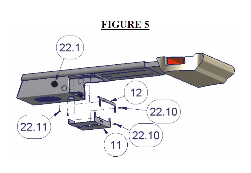
16. Mount the Stereo, CB, or speaker to the removable #11 electronics support frame if desired or your electronic equipment can be fastened directly to the console. Notice that there are holes on the back flange of the bracket for securing a stereo support strap or
similar support device. (See Figure 5)
17. Follow the manufacturer’s directions for connecting the supply wires to your electronic equipment.
18. Slide the #11 Electronics Support Frame into the lockable compartment (you will have to rotate the cam lock while inserting the bracket) and fasten in place using #22.10 (2)6-32 Flat head Screws on the face of the bracket and #22.11 (2) 6-32 Hex Screws up
through the bottom of the console into the bracket. Do not over tighten, these small diameter screws cannot withstand a lot of torque and will break if over-tightened. (See Figure 5)
19. Use the Adjustable Stereo/CB Support Bracket #12 and #22.10 (2) 6-32 Flat Head Screws to secure the top of your electronic equipment. (See Figure 5)
20. Install the (2) 1” Grommets #22.1 in the holes on both sides of the console. A CB microphone or other cables can be routed through the grommet by cutting a slot in the middle of the grommet. (See Figure 5)
21. Reinstall the original #22.12 sound bar using the (6) original screws and then reinstall the top. (See Figure 4)