FREE 1 to 3-Day Delivery on Orders $149+ Details

How to Install Tuffy Series II Speaker/Storage Security Console, Black on your 1997-2006 Wrangler
Tools Required
- (1) 1/2" wrench or ratchet
- socket
- and extension
- (1)1/2 " wrench
- (1) 3/8" wrench or ratchet
- socket
- and extension
- (1) 3/8" socket bit for drill (Used to insert Tapping screws
- OPTION: Hole can be predrilled and the bolt could be
- fastened using a wrench

Shop Parts in this Guide
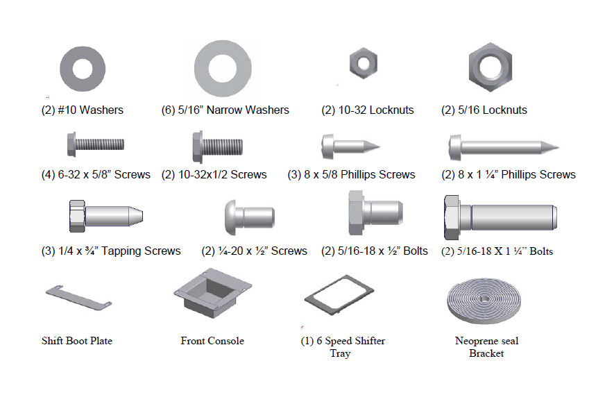
SHIPMENT CONTENTS
Shipping Package
Installation
1. Please read all instructions before starting installation.
2. It is recommended to use silicone sealant on any mounting points to the vehicle body to prevent future rust problems.
3. Removing one or both of the seats will make installation easier.
REMOVING THE ORIGINAL FACTORY CONSOLE
Vehicles already equipped with a factory speaker console
4. Remove the (4) self-tapping screws from the factory console. Two are located inside the rear drink holder under the rubber liner, one is located inside the front drink holder under the rubber insert, and one is under the gear shift boot on vehicles with a manual transmission or it is under the shifter plate on vehicles with an automatic transmission (shift boot or plate can be removed by gently pulling the plastic base up out of its mounting hole and disconnecting the light). Save these screws because you may reuse some of them.
5. Remove the factory console with the speaker box and the front shifter console.
6. Remove the (5) screws holding the speaker box to the factory console. Two are located inside the console, and three are located on the side.
7. In vehicles equipped with the air bag switch it can be removed without disconnecting wires. To do this push or pull the faceplate out of the original console and then maneuver it back through the opening it came out of. In 2003 TJ’s the tray from the original console should be removed and reused.
8. Remove the (2) star washers holding the speaker box to the factory console.
9. Separate the factory console and the speaker box.
Vehicles equipped with a full factory console without the speaker.
10. Remove the (6) self-tapping screws from the factory console. Two are located inside the console, two are on the passenger’s side along the bottom, one is in the front cup holder, and one is under the gear shift boot (shift boot can be removed by gently pulling the plastic base up out of its mounting hole). Save these screws because you may reuse some of them.
11. In vehicles equipped with the air bag switch it can be removed without disconnecting wires. To do this push or pull the faceplate out of the original console and then maneuver it back through the opening it came out of. In 2003 TJ’s the tray from the original console should be removed and reused.
Vehicles not equipped with a factory console only the front shifter console.
12. Remove the rubber emergency brake cover.
13. Remove the screw in the cup holder, and one under the gear shift boot (shift boot can be removed by gently pulling the plastic base up out of its mounting hole). Save these screws because you may reuse some of them.
14. In vehicles equipped with the air bag switch it can be removed without disconnecting wires. To do this push or pull the faceplate out of the original console and then maneuver it back through the opening it came out of. In 2003 TJ’s the tray from the original console should be removed and reused.
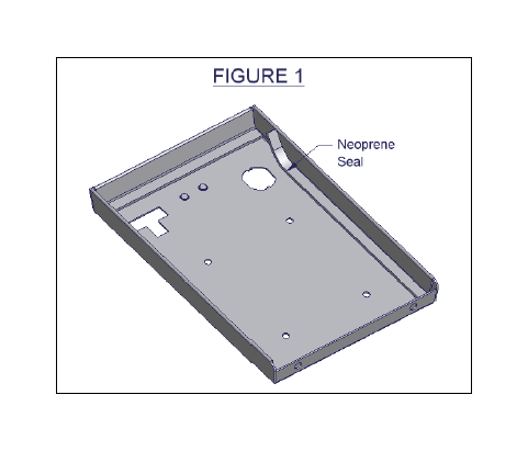
15. Apply the rubber seal to the underside of the lid. (SEE FIGURE 1)
16. Install the front shift lever console over the 4WD shifter. Moving the levers into different locations may make installation easier.
Be sure emergency brake is on. Be careful not to rip the gearshift boot, tear the seats, or scratch the dash.
If the vehicle is equipped with the air bag switch (In 2003 TJ’s the tray from the original console should be used here)
17. The switch can be installed without disconnecting any wires. To do this, maneuver the air bag switch faceplate up from the bottom through the opening in the console then snap it into place.
INSTALLING THE SPEAKER IN THE TUFFY CONSOLE
Follow these steps if you are installing a non-factory speaker in the Tuffy console
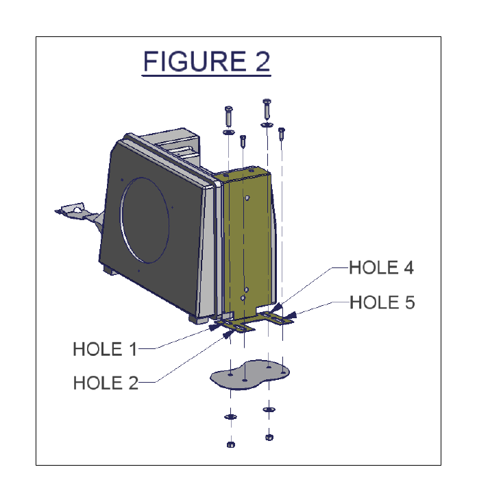
18. Fasten the Tuffy rear mounting bracket through holes 2 and 5 (SEE FIGURE 2) to the original consoles (2) rear mounting holes in the floor, using (2) ¼ X ¾ Tapping screws. Center the screw in the obround slot.
If holes (2 AND 5 IN FIGURE 2) are not already in the floor follow these instructions
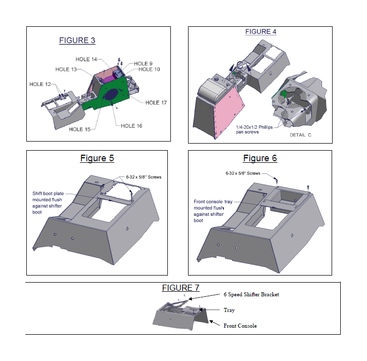
1. Using (2) 5/16 x ½” bolts mount the rear mounting bracket to the console through holes 9 and 10 (SEE FIGURE 3)
2. Place the Tuffy console in the vehicle being careful not to tear the seats. Line up hole 12 (SEE FIGURE 3) in the console with the existing mounting holes in the vehicle floor. Make sure the Tuffy console is centered between the seats and flush against the front shifter console.
3. Install the ¼ x ¾” Tapping screws through holes 2 and 5 (SEE FIGURE 2) and into the floor of the vehicle.
4. Remove the (2) 5/16 x ½ bolts and take out the console. (HOLES 9 AND 10 IN FIGURE 3)
19. Attach the new rear drink holder to the Tuffy console using (2) 10-32 x ½ screws, (2) #10 washers, and (2) 10-32 locknuts. (Continued) Follow these steps if you are installing a non-factory speaker in the Tuffy console
Warning! Make sure that there is nothing under the vehicle that will be damaged by the drill bit when drilling; the emergency brake is close to the drilling location.
20. Mark the floor at the spots corresponding with holes 1 and 4 (SEE FIGURE 2) and drill out to size 3/8”. Be sure to inspect under the vehicle to ensure nothing was damaged by the drill bit.
21. Fasten down the rear mounting bracket with (2) 5/16 x 1 ¼ Bolts, (4) 5/16 Washers, and (2) 5/16 Locknuts through holes 1 and 4 (SEE FIGURE 2).
22. Run the wires and install the speaker in the console. (Consult speaker owners manual for wire connections)
23. Place the Tuffy console in the vehicle being careful not to tear the seats
Follow these steps if you are installing the factory speaker (sub-woofer) in the Tuffy Console
24. Attach the new rear drink holder to the Tuffy console using (2) 10-32 x ½ screws, (2) #10 washers, and (2) 10-32 locknuts.
25. Mount the new rear-mounting bracket to the speaker box. To do this remove the screws holding the original rear bracket to the speaker box, fasten the new mounting bracket using the original hardware. (See Figure 2)
26. Place the speaker box with the mounting bracket in the vehicle and line holes 2 and 5 (SEE FIGURE 2) up with the original (2) rear mounting holes. Center the holes in the obround slots. Using (2) ¼ X ¾” self-tapping screws fasten down the rear brackets to the original mounting holes. DO NOT TIGHTEN ALL THE WAY ONLY START THE SCREWS. If these holes (2 AND 5 IN FIGURE 2) are not already located in the floor, position the console in the vehicle (Be sure to compensate for the space the rear drink holder will require) and drill (2) new holes with the 1/4x3/4 tapping screws, centered in the obround holes 2 and 5.
27. Place the Tuffy console over the top of the speaker box being careful not to tear the seats. Check the alignment for the mounting holes 9, 10, and 12 (SEE FIGURE 3). Adjust speaker box location if necessary.
Warning! Make sure that there is nothing under the vehicle that will be damaged by the drill bit when drilling; the emergency brake is close to the drilling location.
28. Remove console. Mark the floor at the spots corresponding with holes 1 and 4 (SEE FIGURE 2) and drill out to size 3/8”. Be sure to inspect under the vehicle to ensure nothing was damaged by the drill bit.
29. Using (2) 5/16 x 1 ¼ Bolts, (4) 5/16 Washers, and (2) 5/16 Locknuts, fasten the rear mounting bracket to the vehicle through Holes 1 and 4 (SEE FIGURE 2).
30. Install the Tuffy console over the top of the speaker box being careful not to tear the seats.
31. Fasten the Tuffy console to the speaker box using (2) 8 x 1 ¼” Panhead Phillips screws (HOLE 13 AND 14, SEE FIGURE 3) and (3) 8 x 5/8” Panhead Philips screws. (HOLES 15, 16, AND 17, SEE FIGURE 3)
32. Attach the front shift lever console to the drink holder using (2) 1/4-20x1/2” Phillips pan head screws. (SEE FIGURE 4)
33. Bolt the Tuffy console to the new mounting bracket using (2) 5/16 x ½” Bolts and washers. (HOLE 9 AND 10, SEE FIGURE 3) A small screwdriver may need to be used to maneuver the mounting bracket in order to line up the mounting holes.
34. Reinstall the original screw or use a ¼ x ¾” Tapping screw in the front shifter console under the shift boot and insert the shift boot back into its original position. (Use the HOLE 12 that lines up with the original hole, SEE FIGURE 3)
35. Reinstall shift boot cover. If the vehicle has an automatic transmission the shift plate should be installed by pushing the ears on the plate through the corresponding slots in the console then sliding it toward the rear of the vehicle to hold it in place. To secure the shift boot do the following applicable steps.
If the vehicle is equipped with the air bag switch (In 2003 TJ’s the tray from the original console should be used here)
36. Attach the shift boot plate to the console using (2) 6-32 x 5/8 screws (SEE FIGURE 5). Position the shift boot plate flush against shift boot so it holds the shift boot tightly.
If the vehicle is not equipped with the air bag switch 37. Attach the front console tray using (4) 6-32 x 5/8” screws (SEE FIGURE 6). Position the tray flush against the shift boot so it holds the shift boot tightly.
If the vehicle is equipped with a 6 speed manual transmission.
38. Place the front console tray in the cutout. Then sandwich the Original shift boot between the Front Console and the 6 Speed Shifter Bracket. Fasten everything down with (4) 6-32 x 5/8” screws (SEE FIGURE 7).
39. Check the emergency brake operation. Check lock operation. The rubber seal will need to be compressed initially and will wearin with time.
ATTENTION:
FREQUENT LUBRICATION IS NECESSARY ON THE LOCKING SYSTEM
The pushbutton lock contains an “O” ring seal to protect the interior from dust and water. If this mechanism is not lubricated regularly it will become difficult to operate and it may not return to its home position preventing the key from operating the lock. If this happens simply pull up on the pushbutton to manually bring it back to its home position. Lubricate the pushbutton with a light lubricant such as silicone spray. The pushbutton may have to be periodically disassembled and cleaned.