FREE 1 to 3-Day Delivery on Orders $149+ Details

How to Install a Tuffy Delux Security Full Console on your 2011-2014 Wrangler JK
Installation Time
30 minutes
Tools Required
- 18MM Socket and ratchet (To remove seats)
- T-30 Torx bit or driver (To remove OEM console)
- Flat Head Screwdriver (If OEM console has electric window switches in the rear)
- #2 Phillips head screw driver (Short and Long)
- 3/8” Socket and socket wrench and/or open end wrench
- 11/32” Socket and socket wrench and/or wrench
- 3/32” Allen head wrench or bit driver
- Pliers
- Wire cutters (Optional)
- Plastic Trim removal tool (Optional)
- ½” Socket and ratchet
- ½” Open end wrench

Shop Parts in this Guide
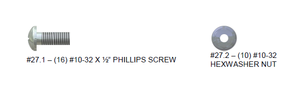
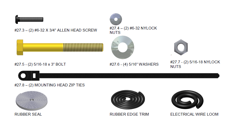
PARTS CHECKLIST
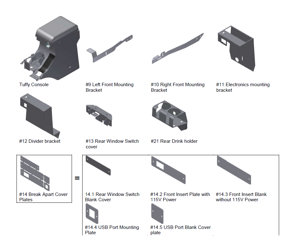
**Individual plates can be broken apart by hand by twisting the parts back and forth. Connecting tabs should then be broken off with pliers by twisting back and forth. Pointed edges should be ground or filed smooth to prevent snagging on other items.
SHIPPING PACKAGE CHECKLIST
ATTENTION:
· THIS CONSOLE WAS DESIGNED FOR A STOCK OEM VEHICLE, ANY MODIFICATIONS MADE MAY AFFECT THE FIT INCLUDING: CARPET REMOVAL/CHANGES, LIFT KITS, SEATS, ETC.
· FREQUENT LUBRICATION IS NECESSARY ON THE LOCKING SYSTEM - The pushbutton lock contains an “O” ring seal to protect the interior from dust and water. If this mechanism is not lubricated regularly it will become difficult to operate and it may not return to its home position preventing the key from operating the lock. If this happens simply pull up on the pushbutton to manually bring it back to its home position. Lubricate the pushbutton with a light lubricant such as silicone spray. The pushbutton may have to be periodically disassembled and cleaned.
PLEASE READ ALL INSTRUCTIONS THOROUGHLY BEFORE STARTING INSTALLATION.
1. IMPORTANT! Make sure the vehicle is parked on a flat surface and place stops behind the wheels to prevent it from rolling. During the installation the vehicle will need to have the emergency brake deactivated, and the 4wd transfer case, Automatic, and manual transmission placed in neutral.
2. The installation will be much easier if the passenger side and/or drivers side seat(s) are unfastened by removing the (4) mounting bolts per seat (Slide the seat forward and reverse for access to bolts). Leave the seatbelts and wiring attached but maneuver the seat to the side making more room for the console removal and installation. The wiring harness may come unplugged (Especially on the driver side); don’t forget to reattach it when refastening the seats or the Jeep will beep constantly. If choosing to complete remove one or both seats, the left and right adjuster tracks can be slid forward/backward independently and the headrest removed in order to make seat removal easier.
3. Place the 4wd transfer case shifter in 4HI or Neutral and remove the shifter knob. Removal of the knob is best achieved by gripping with both hands and pulling it straight off with moderate force. It is not screwed on, do not try to twist and be careful what is behind you because when it comes off you may fly backwards.
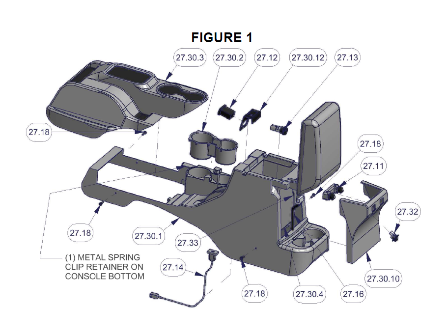
4. Set the parking brake by pulling up as high as it will go. Remove the OEM front console section (Illustrated #27.30.3 – Fig 1) by gripping a corner and pulling firmly up to unclip the (7) plastic trim clips. Take care not to damage the plastic clips. The OEM front console section will be re-used.
5. Remove the (4) Torx screws (#27.18 – Fig 1) securing the OEM bottom console section (Illustrated #27.30.1 – Fig 1). Save the Torx screws as they will be reused. If the console has electric window switches and/or LED courtesy lighting in the rear panel, external 115V power port, internal USB port, or internal 12V power port, follow the applicable instructions below.
If the vehicle has electric window switches mounted in the rear panel: (Illustrated #27.11 – Fig 1)
6. Vehicles with rear electric windows which have switches mounted in the rear panel (Illustrated #27.11 – Fig 1) with a wiring harness (Illustrated #27.16 – Fig 1) will need them removed. .
7. Remove the OEM console rear panel (Illustrated #27.30.10 – Fig 1) by using a plastic trim removal tool to pry the panel loose from the (6) plastic clips. Then unplug the switch harness and remove the switch body from the rear panel using a flat screwdriver or plastic trim tool.
8. Remove the support clamps which attach the wiring harness to the bottom of the original console insert (Illustrated #27.30.4 – Fig 1) by popping them out with a flat head screwdriver. (These may break when removed but they will not be reused). Feed the wiring harness down through the bottom of the OEM console.
If the vehicle has LED courtesy lighting mounted in the rear panel: (Illustrated #27.32 – Fig 1)
9. Vehicles with rear LED lighting which have lamp mounted in the rear panel (Illustrated #27.32 – Fig 1) with a wiring harness (Illustrated #27.33 – Fig 1) will need them removed. .
10. Remove the OEM console rear panel (Illustrated #27.30.10 – Fig 1) by using a plastic trim removal tool to pry the panel loose from the (6) plastic clips. Then unplug the wiring harness and remove the lamp body from the rear panel using a flat screwdriver or plastic trim tool.
11. Remove the wiring harness along with the #27.16 harness by feeding the wiring harness down through the bottom of the OEM console.
If the vehicle has 115V power port mounted in the front panel: (Illustrated #27.12 – Fig 1)
12. Vehicles which feature front external 115V power port (Illustrated 27.12 - Fig 1) will need to remove the power port.
13. Using a plastic trim removal tool, pry up on the front center trim piece (Illustrated #27.30.12 – Fig 1) to free the panel from the (3) plastic clips. Then unplug the 115V power harness and remove the 115V power port from the front panel. Save the power port for reuse.
14. Feed the wiring harness down through the bottom of the OEM console.
If the vehicle has internal USB port mounted in the OEM console insert: (Illustrated #27.14 – Fig 1)
15. Vehicles which feature a USB port (Illustrated #27.14 - Fig 1) will need to remove the USB port.
16. Unclip the USB port from the OEM console insert by releasing the clips and sliding the port towards the driver’s side of the vehicle. OEM console may need to be lifted up slightly to reach the USB port.
17. Unclip the wiring harness from the front middle of the OEM console at the front of the OEM cupholders. Feed the USB port and wiring harness down through the bottom of the OEM console. The USB port will be reused. (The USB “pigtail” cable can be unplugged and removed from the vehicle via the intermediate gray connector located between the transfer case and main shifter housings.)
If the vehicle has internal 12V power port mounted in the OEM console insert: (Illustrated #27.13 – Fig 1)
18. Vehicles which feature 12V power port (Illustrated #27.13 - Fig 1) will need to remove the 12V power port.
19. Unplug the wire harness from the 12V power port and feed the wiring harness down through the bottom of the OEM console. OEM console may need to be lifted up slightly to reach the 12V power port.
20. Remove the 12V power port from the OEM console insert by pressing it out from the rear. Using the palm of your hand, pop the power port firmly from the rear and into the console compartment. Take care not to damage the clips on the side of the power port. 12V power port will be reused.
21. With all accessories removed and all wiring harnesses loose through the bottom of the OEM console, the console (#27.30.1) should be free to be removed. Unclip the (1) metal spring clip retainer (Illustrated in Fig 1) at the front middle of the console (at the shifter housing). Lift the console up and out of the vehicle. Lift the rear up first then maneuver the front up over the emergency parking brake and shift levers.
22. With the console removed from the vehicle, remove and save the OEM front rubber cup holder insert (Illustrated #27.30.2 – Fig 1) by popping out of the retainers at the bottom. Front rubber cup holder will be reused.
If you are installing a Stereo, CB, or other electronic equipment in the console:
23. Run all the required stereo and speaker wires to the console mounting location. Tuffy recommends running wires in a protective wire loom and using rubber grommets when passing through any drilled holes. ATTENTION: Refer to your electronics owner’s manual for instructions on how to mount and wire your electronics.
Stereo mounting note: If a stereo is to be mounted in the console an antenna extension wire will be required and is available at most stereo equipment stores.
CB mounting note: Tuffy recommends mounting an external CB speaker. These are available at most electronics supply stores.
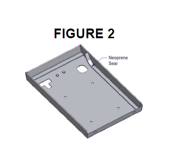
24. Install the Rubber Seal around the inside perimeter of the lid on the flat surface. (Fig 2)
25. Check the lock and latch operation on the Tuffy console.
If the vehicle is equipped with console mounted USB port:
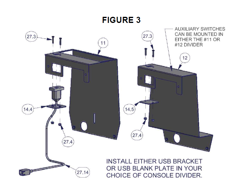
26. Install the USB port “pigtail” (#27.14 – Fig 3) through the #14.4 USB Port Mounting Plate and secure to the underside of the #11 Electronics Mounting bracket or the #12 Divider bracket, as applicable, using the (2) #6-32x3/4” allen head screws (#27.3) and (2) #6-32 nylock nuts (#27.4). Hand tighten. (Fig 3)
27. If not equipped with USB port, install the #14.5 USB Port Blank Cover plate to the underside of the #11 Electronics Mounting bracket or the #12 Divider bracket, as applicable, using the (2) #6-32x3/4” allen head screws and (2) #6-32 nylock nuts. Hand tighten. (Fig 3)
28. If auxiliary switches will be mounted in either the #11 or #12 console divider, install them at this time. (See Fig 3)
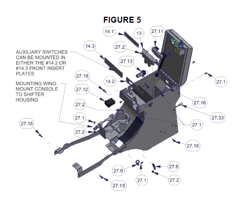
29. If auxiliary switches will be mounted in the #14.2 or #14.3 Front Insert plates, install them at this time. (See Fig 5)
If a Stereo, CB, or other electronic equipment will be mounted in the console:
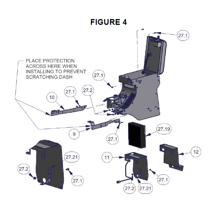
30. Install the electronics (Illustrated #27.19 – Fig 4) in the Electronics mounting bracket (#11 – Fig 4) by using the stereo support strap included with your stereo or CB (Illustrated #27.21 – Fig 4). (If you do not have a stereo support strap, plumber strap may be substituted.) Be sure the body on the electronics is not extending more than 7 13/16” behind the Electronics Mounting Bracket or it will hit the emergency brake assembly.
31. Install the Electronics mounting bracket (#11 – Fig 4) in the console with (4) #10-32 X ½” Phillips screws (#27.1). Check to make sure the lid will still close and latch without causing any problems.
NOTE: Leave the mounting hardware loose for this bracket; it can make installation easier in a later step to unfasten this bracket and gain access under the console (The bracket cannot be removed completely after the console is installed but it can be loosened and moved to the side).
32. If electronic equipment will not be installed using the Electronics mounting bracket (#11 – Fig 4), install the Divider bracket (#12 – Fig 4) in the console with (4) #10-32 X ½” Phillips screws. Do not tighten the hardware at this time.
33. To make installation easier, one or both Front Mounting Brackets (#9 and #10) can be pre-installed to the front of the console using the #10-32 X ½” Phillips screws (#27.1) and #10-32 hexwasher nuts (#27.2). If the driver’s seat was removed, pre-install the right (passenger) side Front Mounting Bracket (#10), conversely, if the passenger’s seat was removed, pre-install the left (driver) side Front Mounting Bracket (#9). Do not tighten the hardware at this time. (Fig 4)
34. Put a protection barrier (like cardboard) between the bottom of the vertical plastic dash console and the front of the Tuffy console when installing to prevent scratches on the dash. (See Fig 4)
35. Install the console into the vehicle by maneuvering it over the shift levers and the emergency brake. Be careful not to scratch the plastic dash or tear the seats. This is best done from the rear seat with two people.
36. Install either of the Front Mounting Brackets (#9 or #10) if remaining at this point. Install with #10-32 X ½” Phillips screws (#27.1) and #10-32 hexwasher nuts (27.2). Start the (2) original OEM mounting Torx screws (#27.18) for the front mounting points. Do not tighten the hardware at this time.
37. Prop the rear of the console up 3-4”. This will make access underneath easier.
Note: The previously installed electronics mounting bracket (#11 – Fig 4) or divider bracket (#12 - Fig 4) can be un-fastened and moved out of the way to improve access for the following steps (It cannot be completely removed at this point).
38. If you are installing electronic equipment inside the console, connect all the wires according to the owner’s manual. Check to make sure the electronic equipment works correctly.
If the vehicle is equipped with rear electric window switches (#27.11 – Fig 5):
39. Feed the rear window switch wire harness (#27.16 – Fig 5) under the console and through the large hole at the bottom rear of the console. Install the electrical wire loom cover over the window switch harness.
40. Feed the wire harness back through the upper part of the hole and into the console compartment. Leave wire harness loose at this point. Ensure that the wire loom protective cover fits into the wire harness slot in the bottom panel of the console compartment to prevent chafing of the wire harness.
If the vehicle has LED courtesy lighting: (Illustrated #27.32 – Fig 5)
41. Feed the rear LED light wire harness (#27.33 – Fig 5) under the console and through the smaller hole at the bottom rear of the console. Leave wire harness loose at this point.
If the vehicle is equipped with console mounted USB port:
42. Plug in the USB port “pigtail” into the USB harness, if equipped.
If the vehicle is equipped with console mounted 12V Power port (#27.13 – Fig 5):
43. Feed the 12V power wire harness through the 12V power hole inside the bottom of the console compartment. Wire harness should be fed through the hole in the #11 or #12 divider, as applicable, then through the hole in the console bottom panel.
44. Plug in the 12V power port (#27.13) and leave loose at this point. Power port will be installed after the divider is final installed.
45. Make sure all the wires and harnesses are fully protected and that nothing will damage them. Wires and harnesses can be fastened into place with the mounting head zip ties (#28.8), #10-32 X ½” Phillips screws (#27.1), and #10-32 hexwasher nuts (#27.2). Mounting holes are provided at the rear of the front drink holder and in the bottom of the console compartment (Fig 5).
If the vehicle is equipped with console mounted 115V Power port (#27.12 – Fig 5):
46. Insert the #14.2 Front Insert Plate with 115V Power between the console and the #11 or #12 divider.
47. Feed the 115V power wire harness through the 115V power port hole in the front console face.
48. Plug in the 115V power port (#27.12 – Fig 5) and leave loose at this point. Power port will be installed after the divider is final installed.
49. If not equipped with 115V Power port, insert the #14.3 Front Insert Blank Plate without 115V Power between the console and the #11 or #12 divider. (Fig 5)
50. Finally, install the #11 or #12 divider with (4) #10-32 X ½” Phillips screws (#27.1) and tighten. (Fig 5)
51. Install the 12V power port into the hole provided and ensure it clips in securely. Install the 115V power port into the hole provided and ensure it clips in securely.
52. Remove any item propping the rear of the console up and start the (2) original OEM mounting torx screws through the holes in the sides and at the rear of the Tuffy console (Illustrated #27.18 – Fig 5). Do not tighten them all the way. (See Fig 5)
53. Align the mounting wing on the front of the console with the retainer clip slot in the shifter housing. Install (1) #10-32 X ½” Phillips screw (#27.1) and (1) #10-32 hexwasher nut (#27.2). Do not tighten the hardware at this time. (Illustrated in Fig 5)
54. If the vehicle is not equipped with the electric rear window switches (#27.11 – Fig 5) then install the 14.1 Rear Window Switch Blank Cover. Install with (2) #10-32 X ½” Phillips screw (#27.1) and (2) #10-32 hexwasher nut (#27.2). Tighten. (Fig 5)
55. If the vehicle is equipped with the electric rear window switches (#27.11 – Fig 5) install them in the Tuffy console using the provided #13 Rear Window Switch cover. Make sure the tabs on the top and bottom of the switches are inserted in the corresponding slots in the Switch cover. The bottom retainer wings on the #13 Switch cover can be gently bent open to allow the switches to drop in, then gently bend the wings back to securely hold the switches from moving within the Switch cover. Plug in the switches to the window switch wire harness inside the console compartment. Install the switches with #13 Switch cover into the rear of the console and fasten with (2) #10-32 X ½” Phillips screws (#27.1) and (2) #10-32 hexwasher nuts (#27.2). Test the switches to make sure they work correctly. (Fig 5)
56. Make sure the 4wd transfer case shifter is in neutral or 4HI, the transmission can be in park, and the emergency brake is activated (pulled up). Be sure vehicle will not roll.
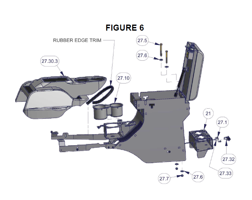
57. Install the OEM front rubber cup holder insert (#27.10 – Fig 6) into the Tuffy console by positioning it into the front drink holder and popping the bottom retainers into the provided holes. Ensure that the side alignment pegs fit into the holes in the front drink holder.
58. Install the Rubber Edge Trim along the bottom rear edge of the OEM front console section (Illustrated #27.30.3 – Fig 6). Trim the Edge Trim as necessary for fitment.
59. Test fit the OEM console front section (Illustrated #27.30.3 – Fig 6) by maneuvering it over the shift levers and the emergency brake. Position the (7) plastic trim clips into the receiving holes and clip into place. If the front of the OEM console section is high or low, remove and adjust the height of the #9 and #10 Front mounting brackets accordingly. Also, the Console can be slid forward or backward a small amount to adjust the fit of the OEM front console section. The OEM front console section should sit level on the transfer case shifter housing and the main shifter housing, and should have only a small gap at the cupholders or the Tuffy console. When satisfied that the OEM front console section fits correctly, remove for final hardware tightening. Take care when installing and removing the OEM front console section not to damage the plastic trim clips.
60. Tighten the (4) original OEM mounting Torx screws (#27.18) and middle (1) #10-32 X ½” Phillips screw (#27.1) and (1) #10-32 hexwasher nut (#27.2) between the console and the shifter housing (Refer to Fig 5 – Mounting Wing). Tighten the (4) #10-32 X ½” Phillips screw (#27.1) and (4) #10-32 hexwasher nut (#27.2) between the #9 and #10 Front Mounting brackets and the console. Final install the OEM console front section (#27.30.3) and clip into place. (Fig 6)
61. Check the emergency brake, 4wd transfer case shifter, and Automatic or Manual transmission shifters. Check to make sure the console locks and functions properly.
OPTIONAL ADDITIONAL SECURITY STEP
62. Install the provided (2) 5/16-18 x 3” bolts (#27.5), (4) 5/16” washers (#27.6), and (2) 5/16” nylock nuts (#27.7) through the provided holes at the bottom rear of the console compartment and through receiving holes in the OEM shifter/ebrake mounting plate underneath the console. There is a long rectangular and a round hole located at the rear of the OEM shifter/e-brake mounting plate that align with the holes in the bottom of the console. One or both of the 5/16” bolts can be installed to provide added security. (Fig 6)
If the vehicle has LED courtesy lighting: (Illustrated #27.32 – Fig 6)
63. Feed the rear LED light wire harness (#27.33 – Fig 5) through the small hole in the #21 Rear Drink Holder and plug in the #27.32 LED light. As the #21 Rear Drink Holder is installed in Step #64, install the #27.32 LED light into the provided hole and make sure it clips into place. (Fig 6).
64. Install the #21 Rear Drink Holder using (2) #10-32 X ½” Phillips screws (#27.1) and tighten. (Fig 6).